Cortical Interface for Motor Signal Recording and Sensory Signal Stimulation

a cortical electrode and motor signal technology, applied in the field of implantable devices, can solve the problems of difficult to achieve the long-term functional stability of intracortical electrodes, require a substantial degree of user training, and are often unreliabl

Active Publication Date: 2012-11-22
CORTIGENT INC
View PDF11 Cites 100 Cited by
  • Summary
  • Abstract
  • Description
  • Claims
  • Application Information

AI Technical Summary

Benefits of technology

[0012]The present invention consists of an implantable device with at least one package that houses electronics that sends and receives data or signals, and optionally power, from an external system through at least one coil attached to at least one package and processes the data, including recordings of neural activity, and/or delivers electrical pulses to neural tissue through at least one array of multiple electrodes that is/are attached to the at least one package. The device is adapted to electrocorticographic (ECoG) and local field potential (LFP) signals. The output signals provide control for a motor prosthesis and the input signals provide sensory feedback for the motor prosthesis. The invention, or

Problems solved by technology

The highest functioning EEG-based BMIs, however, require a substantial degree of user training and their performance is often not reliable.
Though they can achieve a high level of multidimensional of control, there still remains a significant and unresolved question regarding the long-term functional stability of intracortical electrodes, particularly for recording action potentials (Shain 2003; Donoghue 2004; Davids 2006).
This lack of signal durability has important clinical implications, because signal loss would require frequent replacement of the implant which would be neurosurgically unacceptable.
Despite encouraging evidence that current non-invasive and invasive BMI technologies can actually be useful to severely disabled individuals (Kübler 2005; Hochberg 2006; Sellers 2010), these shortcomings and uncertainties remain substantial barriers to widespread clinical adoption and implementation in humans.
However, this system is built

Method used


Image

  • Cortical Interface for Motor Signal Recording and Sensory Signal Stimulation
  • Cortical Interface for Motor Signal Recording and Sensory Signal Stimulation
  • Cortical Interface for Motor Signal Recording and Sensory Signal Stimulation

Examples


Embodiment Construction

[0092]The following description is of the best mode presently contemplated for carrying out the invention. This description is not to be taken in a limiting sense, but is made merely for the purpose of describing the general principles of the invention. The scope of the invention should be determined with reference to the claims.

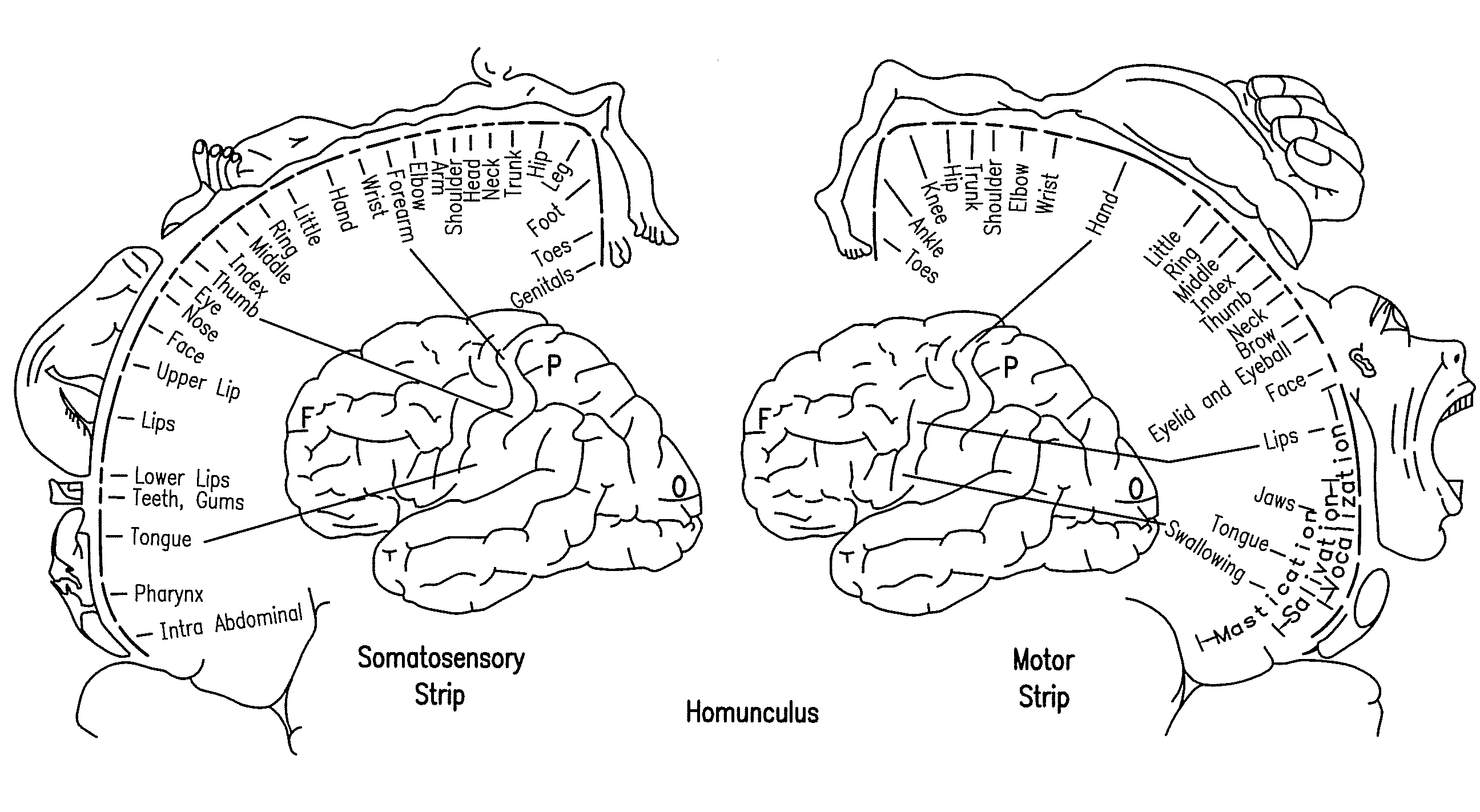
[0093]This application is a cortically driven motor prosthesis: electrodes implanted on or in motor strip, which when activated cause involuntary movements in the subject. The implant provides control for external robotic prosthesis—implant with recording electrodes on or in pre-motor (forward of motor strip) or motor strip, which sends data wirelessly to an external processor which drives a robotic limb (arm, hand, leg, foot) or stimulates muscles in a deinervated arm, hand, leg, foot, face, tongue, etc.)

motor signal neural recorder and a somatosensory prosthesis providing motor control and external or implantable sensors that respond to—

a. Pressure

b. Tempe...


PUM

PropertyMeasurementUnit
Flexibilityaaaaaaaaaa

Abstract

The present invention consists of an implantable device with at least one package that houses electronics that sends and receives data or signals, and optionally power, from an external system through at least one coil attached to the at least one package and processes the data, including recordings of neural activity, and delivers electrical pulses to neural tissue through at least one array of multiple electrodes that is/are attached to the at least one package. The device is adapted to electrocorticographic (ECoG) and local field potential (LFP) signals. The output signals provide control for a motor prosthesis and the inputs signals provide sensory feedback for the motor prosthesis. The invention, or components thereof, is/are intended to be installed in the head, or on or in the cranium or on the dura, or on or in the brain.

Description

CROSS REFERENCE TO RELATED APPLICATIONS[0001]This application is related to and incorporates by reference U.S. Patent application 2009 / 0124965, for Implantable Device for the Brain, filed Jul. 25, 2008.FIELD OF THE INVENTION[0002]The present invention is an implantable device for interfacing with neural tissue, primarily in order to record neural activity for the control of a motor prosthesis. Secondarily the implantable devices stimulates neural tissue to provide sensory feedback.BACKGROUND OF THE INVENTION[0003]Neural tissue can be artificially recorded from and stimulated by prosthetic devices that sense or pass pulses of electrical current through electrodes on such a device. The passage of current causes changes in electrical potentials across neuronal membranes, which can initiate neuron action potentials, which are the means of information transfer in the nervous system.[0004]Based on this mechanism, it is possible to read information from and input information into the centr...

Claims


Application Information

Patent Timeline
IPC IPC(8): A61F2/72A61N1/04A61B5/0476
CPCA61B5/4064H01L2224/85099A61N1/0531A61N1/0534A61N1/0539A61N1/36082A61N1/375H05K1/118H05K1/189H05K2201/0154H05K2201/10098H01L2224/45144A61B5/6868H01L2924/3011H01L2224/48465H01L2224/48227A61B5/04001H01L2924/00H01L2224/05599H01L2224/85399A61N1/37518A61N1/37514A61B5/24H01L2924/00014
Inventor GREENBERG, ROBERT J.ZHOU, DAVID DAOMINMECH, BRIAN V.TALBOT, NEIL HAMILTONDAI, RONGQINGCASTRO, RICHARD AGUSTINMCCLURE, KELLY H.
Owner CORTIGENT INC
Why Eureka
Try Eureka