Dissimilar metal welds and its manufacturing method of large welded structures such as the turbine rotor

a technology of dissimilar metal welds and manufacturing methods, which is applied in the direction of non-electric welding apparatus, machines/engines, fastening means, etc., can solve the problems of deterioration in strength reliability, difficulty in obtaining characteristics that satisfy, and inability to alleviate the uneven strength caused by heat treatment. , to achieve the effect of improving strength reliability and preventing the deterioration of welding metal strength

Inactive Publication Date: 2012-11-29
MITSUBISHI HITACHIPOWER SYST LTD
View PDF6 Cites 18 Cited by
  • Summary
  • Abstract
  • Description
  • Claims
  • Application Information

AI Technical Summary

Benefits of technology

[0014]According to the present invention, buttering is formed of welding metals laminating in a plate thickness direction, and the dilution ratio of the bottom of the buttering portion and the oxygen concentration of the surface layer portion of the buttering portion are low, which makes it possible to set the dilution ratio to 50% or less. Consequently, it is possible to provide an effect of preventing the deterioration in strength of the welding metal due to an increased in oxygen concentration, and improving the strength reliability of large welded structures such as the turbine rotor.

Problems solved by technology

Some large welded structures are laterally placed and welded due to limitations of deformation of their shapes, work space, and the like.
Therefore, in the case of forming a steam turbine rotor using one member, it has been difficult to obtain characteristics that satisfy these demands.
For this reason, the effect of alleviating the unevenness of the strength caused by heat treatment cannot be expected.
In the dissimilar metal welds including the buttering portion disclosed in JP Patent Application Publication No. 2001-123801, JP Patent Application Publication No. 2000-64805, and JP Patent Examined Application Publication No. 6-78721, a laminated direction of a buttering is perpendicular to the plate thickness of the parent material and thus coincides with a stress loading direction, leading to deterioration in strength reliability.
As a result, the shielding effect is reduced and the oxygen concentration of the welding metal is increased, leading to deterioration in strength.
Further, in the dissimilar metal welds including a buttering layer disclosed in JP Patent Application Publication No. 2007-278064, the bottom of the buttering is located in a butt portion with great dilution between the welding metal and the parent material, which deteriorates the strength reliability.
Thus, there is a problem of deterioration in strength due to an increase in oxygen concentration of the welding metal.

Method used


Image

  • Dissimilar metal welds and its manufacturing method of large welded structures such as the turbine rotor
  • Dissimilar metal welds and its manufacturing method of large welded structures such as the turbine rotor
  • Dissimilar metal welds and its manufacturing method of large welded structures such as the turbine rotor

Examples


example 1

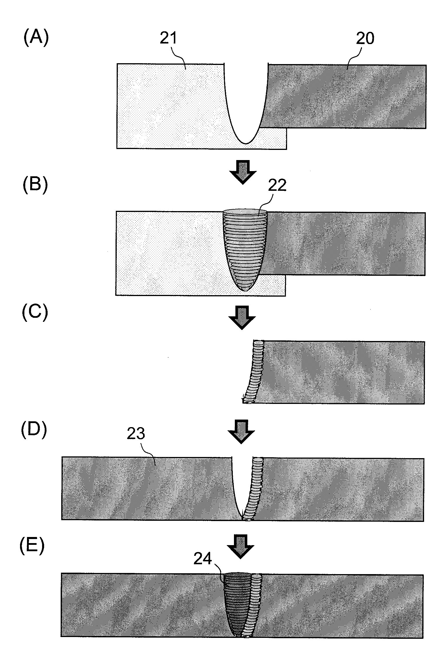
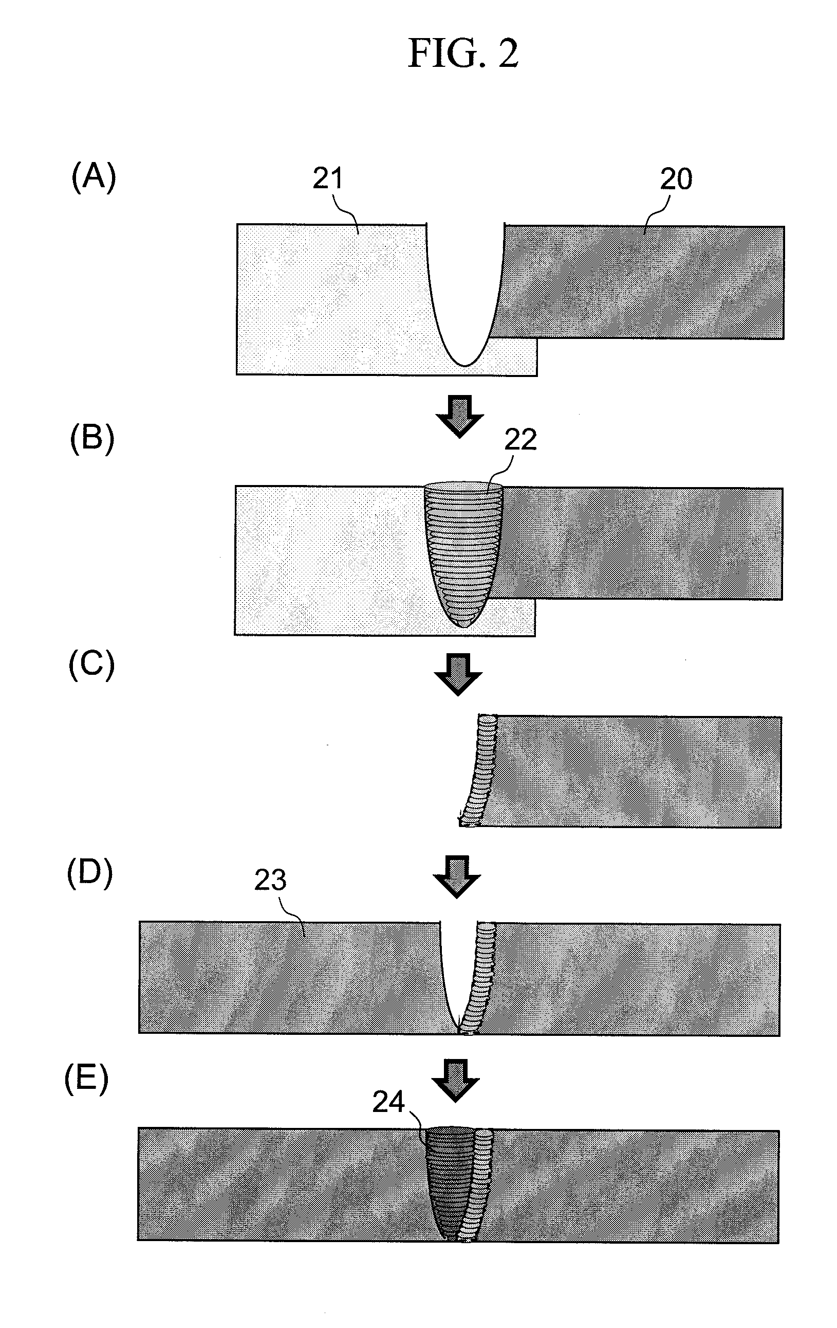
[0026]Example 1 of the present invention will be described below with reference to FIGS. 1 to 6. Though Example 1 illustrates dismissal metal welds of a turbine rotor as dissimilar metal welds, dissimilar metal welds of other product may also be used. The specifications and composition ranges of two dissimilar metals forming the welds are shown in the following Table 1. Example 1 uses an Ni-base superalloy and 12%-Cr steel from Table 1, and these components constitute the dissimilar metal welds.

TABLE 1Kinds of steelsCMnNiCrMoWNbCoBNi-base superalloy0.05~0.20bal. 13~15.50.1~2.04.5~10 0.1~1.05~150.001~0.03Ni—Fe-base≦0.05bal.14~161.9~2.7superalloy12% Cr steel0.1~0.20.3~1.0≦1 9~130.1~1.50.2~5.00.02~0.1 ≦31% Cr—Mo—V steel 0.25~0..350.5~1 ≦10.8~1.51.0~1.53~4% Ni—Cr—Mo—V-0.17~0.320.2~0.43~41.25~2.0 0.25~0.60based steelKinds of steelsVTiAlTaHfZrFeNi-base superalloy0.1~2.04.0~5.50.1~3.00.1~2.00.01~0.1Ni—Fe-base1.2~1.71.1~1.530~40superalloy12% Cr steelbal.1% Cr—Mo—V steel0.2~0.3bal.3~4% Ni—Cr...

example 2

[0046]Example 2 according to the present invention will be described with reference to FIG. 8, (A) to (E). Example 1 has characteristics involving the shape on the bottom side of the weld in the manufacturing method of the dissimilar metal welds, whereas Example 2 has characteristics involving the bottom side as well as the opening side of the weld in the manufacturing method of the dissimilar metal welds. The description of the characteristics identical with those of the Example 1 is herein omitted and only the differences from Example 1 will be described below.

[0047]FIG. 8, (A) to (E), shows a manufacturing flow of welding two members made of different materials according to Example 2. Example 2 differs from Example 1 only in FIGS. 8, (A) and (B). FIG. 8 (A) shows the state of the step of butting the parent material 20 and the dummy material 21. In the vicinity of the opening of each of the parent material 20 and the dummy material 21, a shielding plate 25 is mounted to increase t...

example 3

[0049]Example 3 according to the present invention will be described with reference to FIG. 9, (A) to (E). An Ni-base superalloy and 1%-Cr—Mo—V-based steel are used as two dissimilar metals in Example 3. Example 2 relates to the shape on the bottom side of the weld in the manufacturing method of the dissimilar metal welds, whereas Example 3 relates to the material on the bottom side. The description of the characteristics identical with those of the Example 2 is omitted, and only the differences from Example 2 will be described below.

[0050]FIG. 9, (A) to (E), shows a manufacturing flow of welding two members made of different materials according to Example 3. Example 3 differs from Example 2 only in FIGS. 9 (A) and (B). FIG. 9 (A) shows the step of butting the parent material 20 and the dummy material 21. In the vicinity of the weld bottom, the dummy material 21 and the parent material 20 have the same plate thickness. At a position apart from the vicinity thereof, the dummy materia...


PUM

PropertyMeasurementUnit
thicknessaaaaaaaaaa
lengthaaaaaaaaaa
plate thicknessaaaaaaaaaa

Abstract

Dissimilar metal welds including a buttering portion with a small variation in strength distribution in a plate thickness direction are formed by welding two parent materials having at least one of different compositions and different refining conditions through a buttering for alleviating mismatch between one of the different compositions and the different refining conditions of the two members and through a welded metal for joining one of the parent materials and the buttering. The buttering is formed of welding metals laminated in a plate thickness direction, and a dilution ratio of the buttering with the parent materials is 50% or less. The manufacturing method includes performing butt welding on a dummy material formed by increasing a groove depth by providing a member on a bottom side of a welding groove and on parent materials by using the buttering; and processing a groove within a welding metal formed of the buttering.

Description

BACKGROUND OF THE INVENTION[0001]1. Field of the Invention[0002]The present invention relates to dissimilar metal welds and its manufacturing method, and more particularly, to a product obtained by welding and integrating two different materials of large welded structures such as the turbine rotor, and its manufacturing method.[0003]2. Background Art[0004]Some large welded structures are laterally placed and welded due to limitations of deformation of their shapes, work space, and the like. Examples of the structures include a turbine rotor to be welded. In general, a large steam turbine rotor has a large shaft length. In addition, a high-pressure-side rotor is required to have a high-temperature creep rupture strength, and a low-pressure-side rotor is required to have a tension strength and toughness. Therefore, in the case of forming a steam turbine rotor using one member, it has been difficult to obtain characteristics that satisfy these demands. In this regard, there is known a ...

Claims


Application Information

Patent Timeline
Patent Type & Authority Applications(United States)
IPC IPC(8): F04D29/38B23K1/19B23K28/00B23K101/00
CPCB23K9/0026B23K9/0282B23K9/046B23K9/173B23K9/232B23K9/235Y10T29/4932B23K2201/06B23K2203/18F01D5/063F05D2230/232F05D2300/50212Y10T403/479B23K2201/001B23K2101/001B23K2101/06B23K2103/18B23K2103/26
Inventor NISHIOKA, EIJISATO, JUNIMANO, SHINYAKUDO, TAKESHIMURATA, KENICHIHOSOKAWA, KAZUTAKAENDO, KAZUHIKO
Owner MITSUBISHI HITACHIPOWER SYST LTD
Why Eureka
Try Eureka