
Separators for a lithium ion battery

Active Publication Date: 2012-12-06
GM GLOBAL TECH OPERATIONS LLC
View PDF2 Cites 52 Cited by
  • Summary
  • Abstract
  • Description
  • Claims
  • Application Information

AI Technical Summary

Benefits of technology

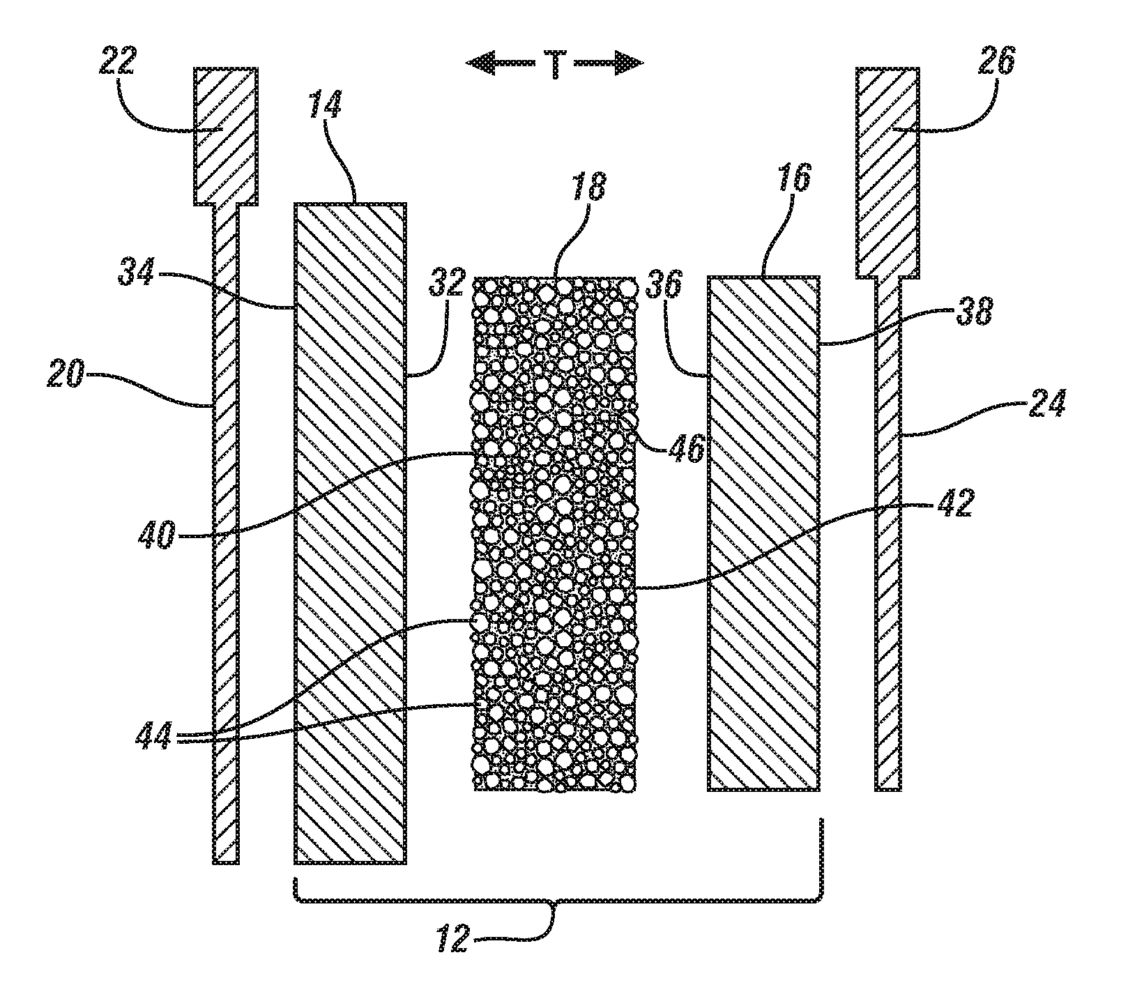
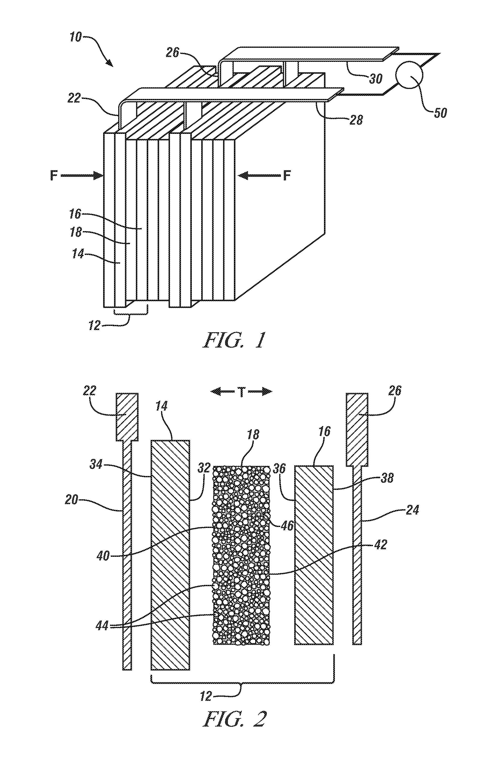
[0011]The separator is intended to be used in the assembly of an electrochemical battery cell for a lithium ion battery. The separator may be situated between a negative electrode and a positive electrode and be infiltrated with an appropriate liquid electrolyte solution. The heat-resistant particles present on the major face surfaces of the separator contact confronting inner face surfaces of the negative and positive electrodes under an applied compressive force. The separator electrically insulates and physically separates the electrodes to prevent a short-circuit while remaining permeable to the internal passage of lithium ions (and related anions) through the liquid electrolyte solution. When assembled, the entire thickness of the electrochemical cell (positive electrode, negative electrode, and separator) is usually between about 80 μm and about 350 μm. A plurality of these electrochemical cells, often numbering from 10 to 150, can be connected in series or in parallel with many other electrochemical cells to form a lithium ion battery which, in turn, can be connected in series or in parallel with several other lithium ion batteries to form a lithium ion battery pack. The relatively thin and flexible nature of the electrochemical cells allows them to be rolled, folded, bent, or otherwise maneuvered into a variety of lithium ion battery configurations depending on design specifications and spatial constraints.
[0012]The high content of the heat-resistant particles amassed between the confronting inner face surfaces of the electrodes provides the separator with robust thermal stability well above 130° C. The heat-resistant particles will not soften, melt, swell, or chemically react with the liquid electrolyte solution even at the extreme ends of the conceivable operating temperature window of the lithium ion battery; rather, they remain compressed in place between the confronting inner face surfaces of the negative and positive electrodes. Nor will the heat-resistant particles sacrifice lithium ion conductivity at normal or elevated temperatures. The lithium ions can migrate around the heat-resistant particles and through the porous inert polymer material without much resistance. This is because the very small size of dissolved lithium ions in the liquid electrolyte solution can easily traverse the pore openings contained in the porous inert polymer material.
[0013]The fact that the porous inert polymer material may soften or melt at elevated temperatures (i.e., above 100° C.) does not significantly impact the structure or functionality of the separator. As mentioned before, the separator is compressed between the negative electrode and the positive electrode by an applied compressive force to promote intimate contact between the separator and each electrode at their respective contacting interfaces. The applied compressive force is also sufficient to prevent collapse or fragmentation of the heat-resistant particles that mostly constitute the separator should the porous inert polymer material that binds the many particles together soften or melt. The compressive and frictional forces acting on the heat-resistant particles are generally strong enough to withstand the effects of volumetric, structural, and / or phase changes that may occur in the porous inert polymer material. In fact, upon softening or melting, the porous inert polymer material would likely stay confined to a localized spatial volume defined by surrounding heat-resistant particles and then re-solidify when the temperature falls to a sufficient extent.
[0014]The separator can be fabricated by a phase-separation process in which the porous inert polymer material is precipitated out of a polymer solution that has been imbibed into the interstices of a layer of the heat-resistant particles. The free-standing separator produced by this process is handleable and can be assembled into an electrochemical battery cell between the negative and positive electrodes by conventional techniques without falling apart. The separator is situated between the negative and positive electrodes under an applied compressive force so that the heat-resistant particles extend between the confronting inner face surfaces of the electrodes to provide a porous and non-electrically conductive physical barrier. The porous inert polymer material contained in the separator allows the separator to be handled and situated between the electrodes during assembly of the electrochemical battery cell.

Problems solved by technology

Nor will the heat-resistant particles sacrifice lithium ion conductivity at normal or elevated temperatures.

Method used


Image

  • Separators for a lithium ion battery
  • Separators for a lithium ion battery
  • Separators for a lithium ion battery

Examples


example

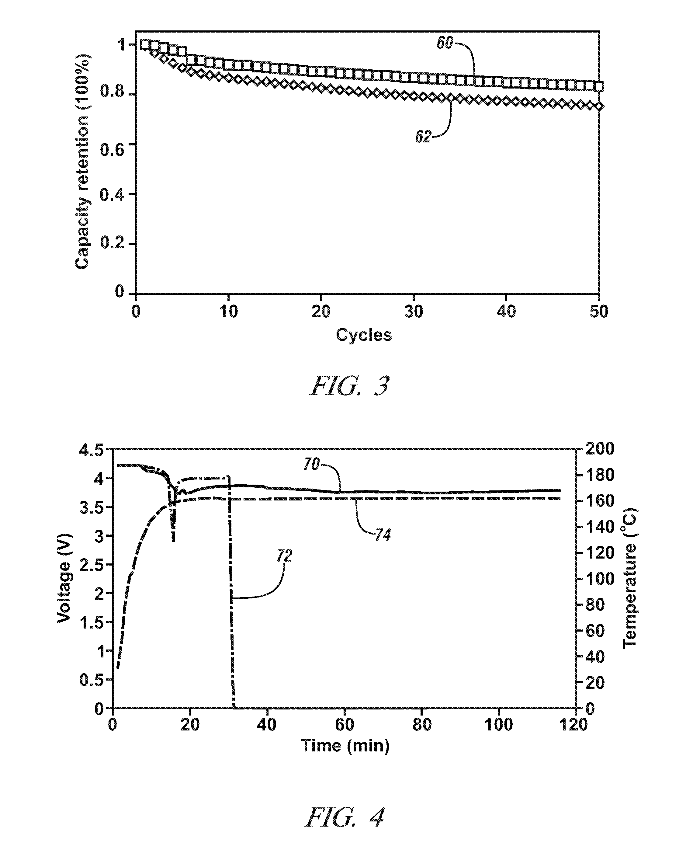
[0041]This Example demonstrates the ionic conductivity, electrochemical cell cycle performance, and thermal stability of a separator comprised predominantly of heat resistant-particles, as described above, in comparison to a conventional monolayer polypropylene lithium ion battery separator obtained from Celgard, LLC (Charlotte, N.C.). The separator comprised predominantly of the heat-resistant particles is referred to in the remainder of this Example as the “inventive separator” for brevity.

[0042]The inventive separator was formed by a phase separation process, as described above. To begin, alumina particles having a diameter of 1 μm were dispersed in dimethylforamide (DMF). The dispersion of alumina particles was then spread on a glass plate using a doctor blade. The glass plate was placed in an oven set at 80° C. and the DMF was evaporated to form a layer of the alumina particles. A polymer solution that contained 5 wt. % polyvinyldiene fluoride (PVdF) dissolved in a miscible sol...


PUM

PropertyMeasurementUnit
Lengthaaaaaaaaaa
Lengthaaaaaaaaaa
Lengthaaaaaaaaaa

Abstract

A separator for use in a lithium ion battery to provide a physical and electrically insulative mechanical barrier between confronting inner face surfaces of a negative electrode and a positive electrode may be formed predominantly of heat-resistant particles. The heat-resistant particles, which have diameters that range from about 0.01 μm to about 10 μm, are held together as a thin-layered, handleable, and unified mass by a porous inert polymer material. The high content of heat-resistant particles amassed between the confronting inner face surfaces of the negative and positive electrodes provides the separator with robust thermal stability at elevated temperatures. Methods for making these types of separators by a phase-separation process are also disclosed.

Description

TECHNICAL FIELD[0001]The technical field of this disclosure relates generally to separators for a secondary lithium ion battery and, more specifically, to a separator formed predominantly of heat-resistant particles. The many heat-resistant particles are held together as a thin-layered, handleable, and unified mass by a porous inert polymer material. In an electrochemical battery cell of a lithium ion battery, the separator is situated between confronting inner face surfaces of a positive electrode and a negative electrode under an applied compressive force. Methods for making this type of separator by phase-separation are also disclosed.BACKGROUND[0002]Secondary (i.e., rechargeable) lithium ion batteries have been implemented as a power source into a wide variety of stationary and portable applications. Their structure and electrochemical reaction mechanism provide them with several desirable characteristics including a relatively high energy density, a relatively low internal resi...

Claims


Application Information

Patent Timeline
IPC IPC(8): H01M2/16H01M10/02B29C67/20H01M50/403H01M50/406H01M50/42H01M50/426H01M50/491H01M50/497
CPCY02E60/122Y02T10/7011H01M2/145H01M10/0566H01M2/348H01M10/0525H01M2/166Y02E60/10H01M50/446H01M50/403H01M50/581H01M50/406H01M50/491H01M50/426H01M50/497H01M50/42Y02T10/70H01M50/46
Inventor HUANG, XIAOSONG
Owner GM GLOBAL TECH OPERATIONS LLC
Learn More