
Medical Catheter With Bump Tubing Proximal Segment

a technology of proximal segment and catheter, which is applied in the field of medical catheters with multiple stiffness sections, can solve the problems of previous markers being subject to wear and other damage, and the potential site of catheter kinking, etc., and achieve the effects of improving flexibility, improving performance, and increasing the coefficient of friction

Active Publication Date: 2012-12-06
TERUMO MEDICAL CORP
View PDF3 Cites 8 Cited by
  • Summary
  • Abstract
  • Description
  • Claims
  • Application Information

AI Technical Summary

Benefits of technology

The present invention relates to a catheter design that improves performance by using a transition zone with increasing flexibility. This transition zone is located proximal to the distal tip and has a decreasing inside and outside diameter, providing a gradual increase in flexibility towards the distal end. The distal tip has a substantially constant stiffness and flexural modulus, and a distal cover protects any radiopaque markers. The catheter can be joined with separate components using a fusing process with reduced kinking. The technical effects of this design include improved flexibility, reduced kinking, and improved performance of the catheter.

Problems solved by technology

However, mechanical bonding or welding of the different sections creates a potential site for kinking of the catheter.
However, previous markers have been subject to wear and other damage while passing through particularly tortuous anatomies.

Method used


Image

  • Medical Catheter With Bump Tubing Proximal Segment
  • Medical Catheter With Bump Tubing Proximal Segment
  • Medical Catheter With Bump Tubing Proximal Segment

Examples


Embodiment Construction

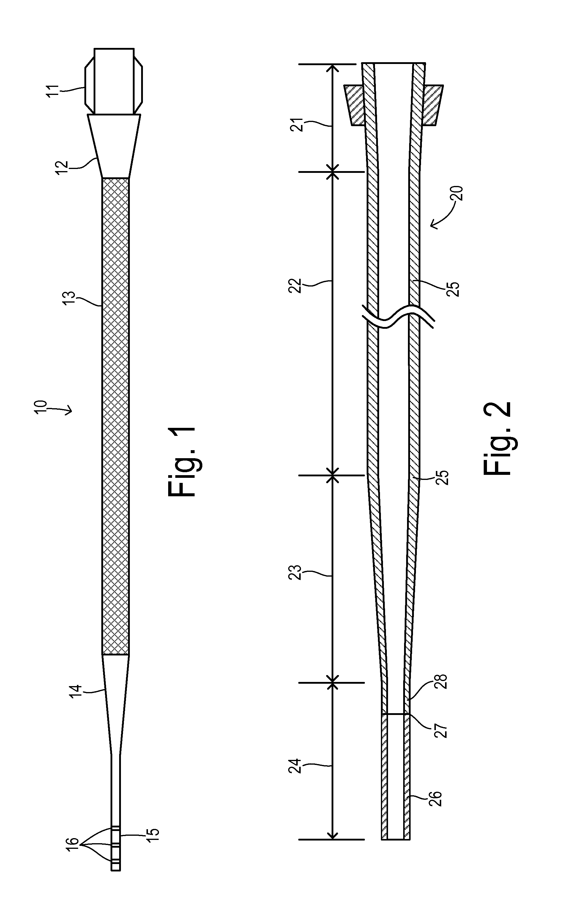
[0022]Referring now to FIG. 1, a catheter 10 has a proximal end having a hub 11 and a stress release section 12 of conventional design. A bump tubing section spanning the major portion of catheter 10 includes an intermediate portion 13 with a substantially constant outer diameter and thickness and a taper portion 14 with a generally decreasing inside and outside diameter to provide a gradually increasing flexibility toward the distal end of the bump tubing section. As shown in FIG. 1, the intermediate portion may include a conventional braided or coiled material around the bump tubing section for increasing stiffness and pushability.

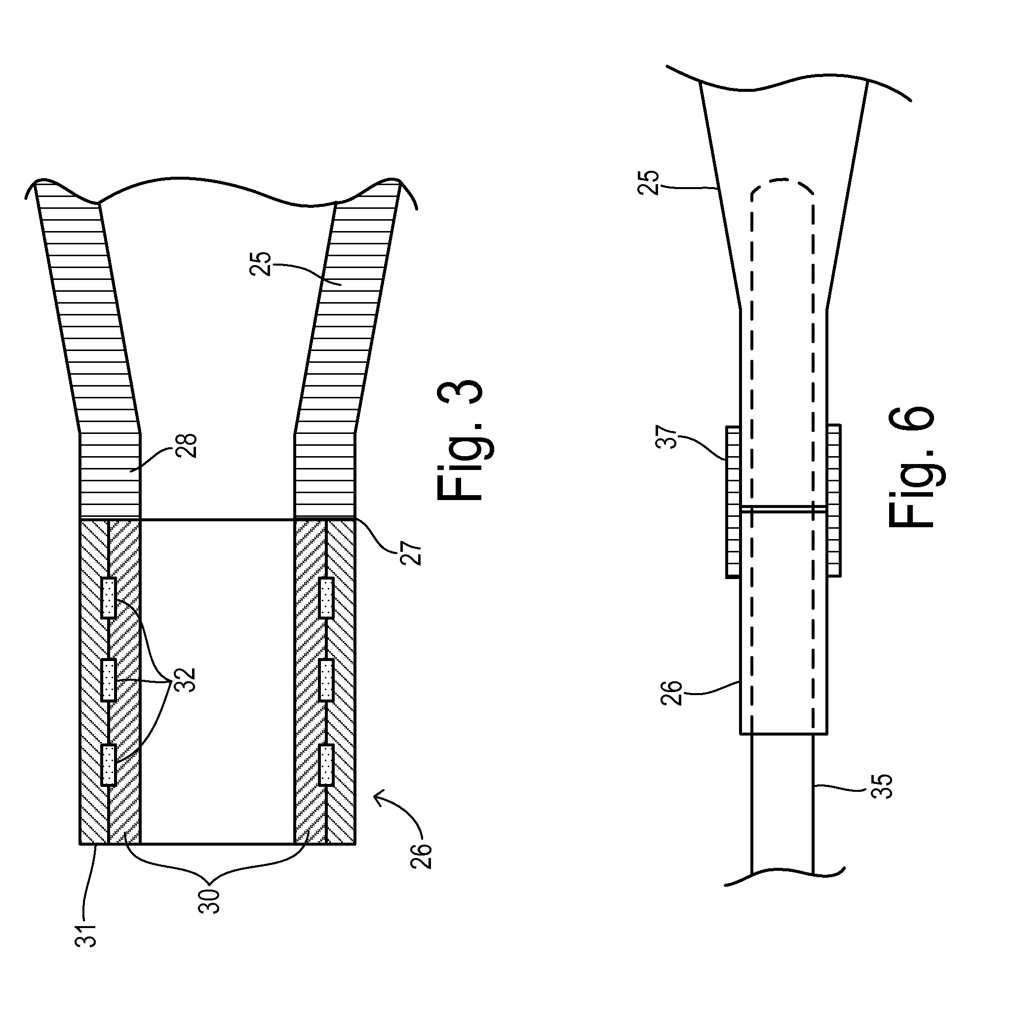
[0023]A tip section 15 is disposed distally of the bump tubing section and is made from a material having a flexural modulus substantially equal to or greater than the flexural modulus of the material in the taper section 14. In one embodiment, both can be made from the same material. A plurality of radiopaque markers 16 are provided within distal tip 15...


PUM

PropertyMeasurementUnit
flexural modulusaaaaaaaaaa
diameteraaaaaaaaaa
diameteraaaaaaaaaa

Abstract

A medical catheter for inserting into a body includes a bump tubing section with proximal and distal ends, wherein the proximal end is configured to mate with a hub. The bump tubing section has an intermediate portion extending away from the proximal end with a substantially constant outer diameter and thickness, and a taper portion adjacent the distal end with generally decreasing inside and outside diameters to provide a gradually increasing flexibility toward the distal end of the bump tubing section. The bump tubing section is comprised of a polymer having a predetermined flexural modulus. A tip section is disposed distally of the distal end of the bump tubing section comprising a distal liner and a distal cover such that at least a majority of the tip section has a substantially constant stiffness and a flexural modulus substantially equal to or greater than the predetermined flexural modulus.

Description

CROSS REFERENCE TO RELATED APPLICATIONS[0001]Not Applicable.STATEMENT REGARDING FEDERALLY SPONSORED RESEARCH[0002]Not Applicable.BACKGROUND OF THE INVENTION[0003]The present invention relates in general to a medical catheter with multiple stiffness sections, and, more specifically, to a medical catheter and an efficient manufacturing method employing bump tubing and a relatively stiffened distal end incorporating radiopaque markers.[0004]Many medical procedures require entry into a patient's blood vessel for purposes of accessing a desired site, e.g., angioplasty, stenting, and other treatments for chronic total occlusions. In order to gain access to the desired site, a catheter is advanced through the blood vessel. Once in place within the patient's vessel, various types of medical instrumentation can be fed through the catheter and positioned at the desired site so that the procedure may be performed.[0005]To initially gain access to a particular site within a patient, a needle is...

Claims


Application Information

Patent Timeline
Patent Type & Authority Applications(United States)
IPC IPC(8): A61M25/00B29C65/02A61M25/098
CPCB29C66/5344B29C66/63A61M25/0012B29C65/02B29C65/48A61M25/005A61M25/0054B29C65/1425A61M25/001B29C65/08B29C65/16B29C66/53241B29C65/04Y10T156/1013B29C66/1142B29C65/06B29L2031/7542B29C65/68A61M25/0108B29C66/71B29K2021/003B29K2023/00B29K2023/06B29K2023/10B29K2023/12B29K2027/12B29K2077/00
Inventor KRONFELD, ALEX M.NORTON, DEREK L.YOUNG, ROBIN M.
Owner TERUMO MEDICAL CORP
Learn More