Methods for manufacturing implants having integration surfaces

Inactive Publication Date: 2012-12-13
TITAN SPINE
View PDF11 Cites 50 Cited by
  • Summary
  • Abstract
  • Description
  • Claims
  • Application Information

AI Technical Summary

Benefits of technology

[0015]The resulting implant, for a solid body implant or a composite implant, comprises at least one integration surface having a roughened surface topography where the entire implant or the integration plate was produced by such a process that the surfaces and edges of the implant are of high quality and re

Problems solved by technology

Over time, the discs may become diseased or infected, may develop deformities such as tears or cracks, or may simply lose structural integrity (e.g., the discs may bulge or flatten).
Impaired discs can affect the anatomical functions of the vertebrae, due to the resultant lack of proper biomechanical support, and are often associated with chronic back pain.
There are a number of problems, however, with traditional spinal implants including, but not limited to, improper seating of the implant, implant subsidence (defined as sinking or settling) into the softer cancellous bone of the vertebral body, poor biomechanical integrity of the endplates, damaging critical bone structures during or after implantati

Method used


Image

  • Methods for manufacturing implants having integration surfaces
  • Methods for manufacturing implants having integration surfaces
  • Methods for manufacturing implants having integration surfaces

Examples


Embodiment Construction

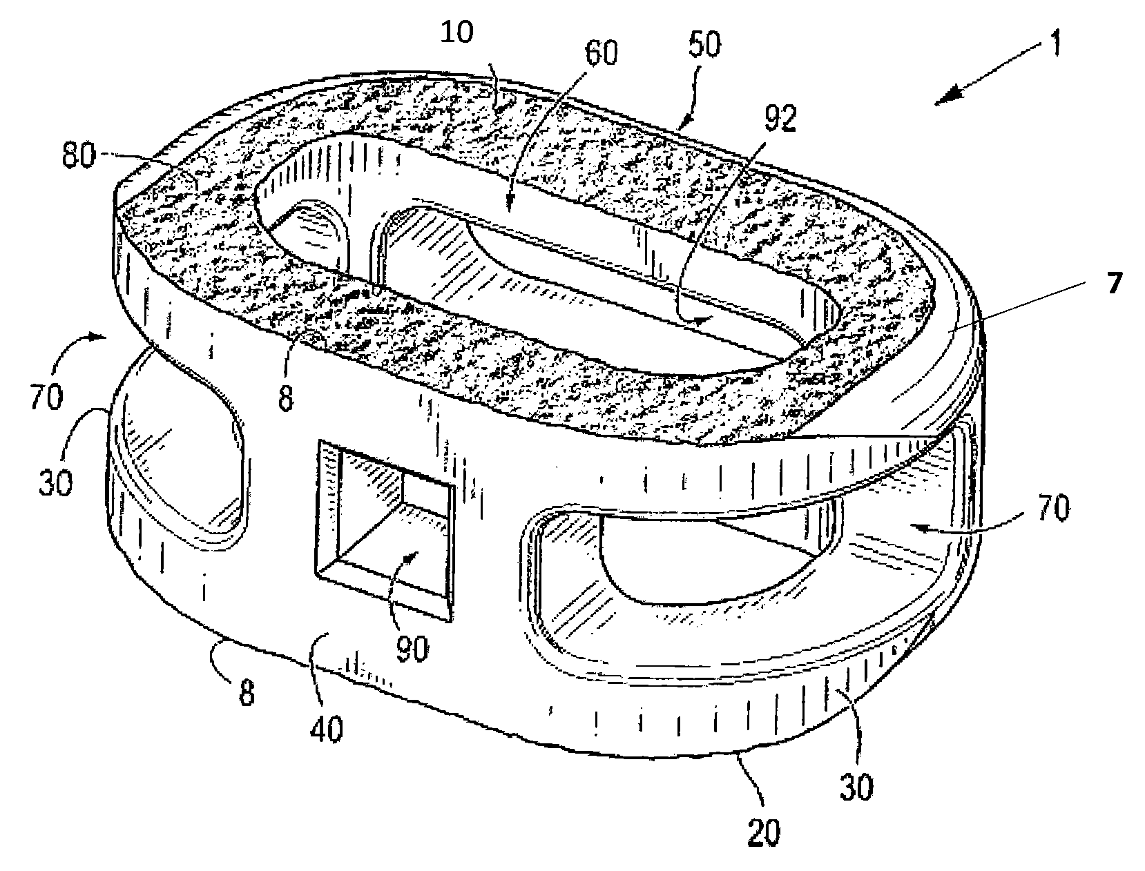
[0039]The present invention provides for interbody spinal implants, including solid body implants and composite implants, produced by fewer process steps and fewer transitions during the manufacturing process. The dimensions and surface features of the implant may be produced in a very accurate and repeatable manner without bleeding (e.g., bleeding of the acid etchant) or poor quality at the edges or interfaces between areas with different surface features (e.g., roughened topography versus substantially smooth surfaces).

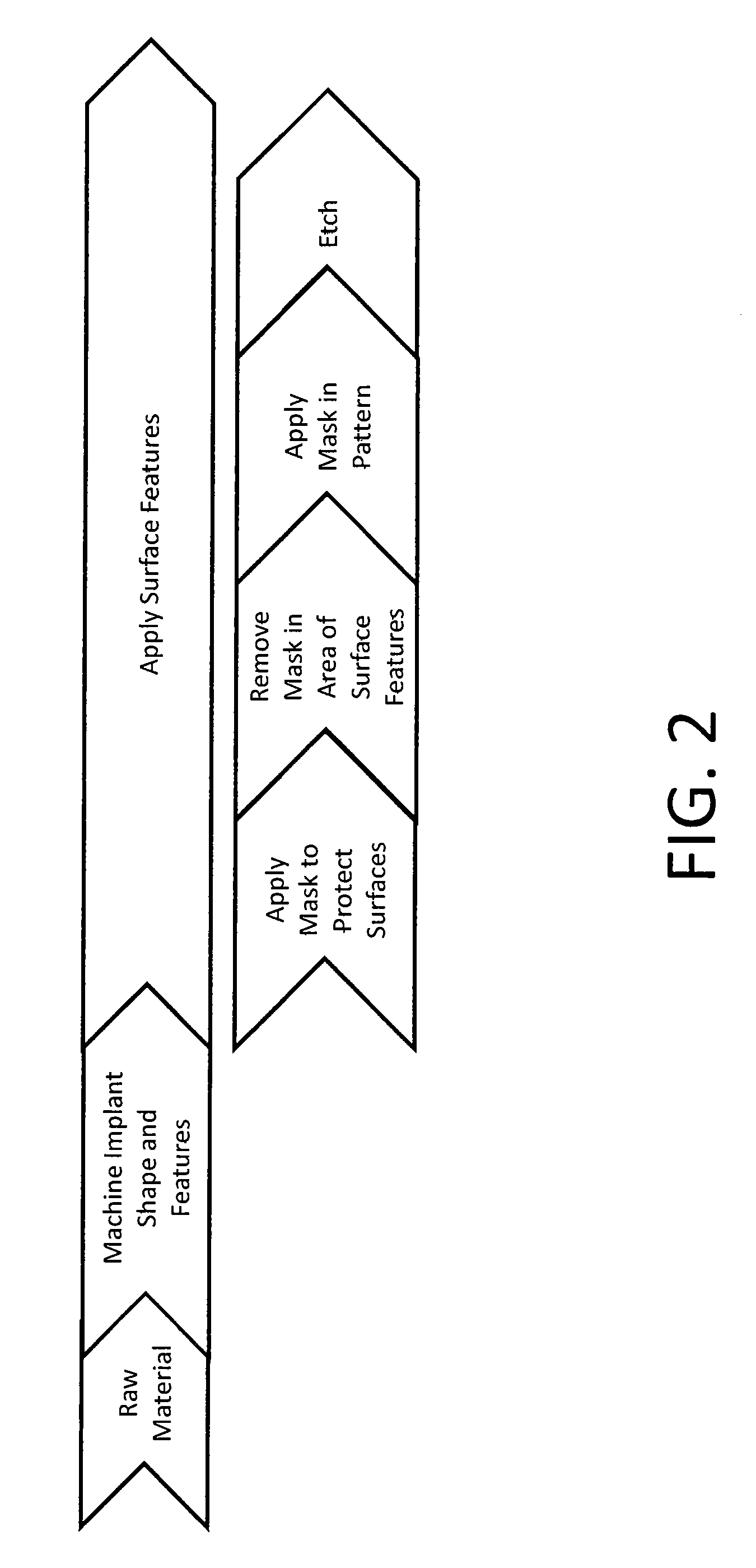
[0040]Under common manufacturing techniques, an implant may be produced by machining the implant from a raw material and, after the implant is produced, applying any surface processing to the surfaces requiring such treatment. Referring to the drawing, in which like reference numbers refer to like elements throughout the various figures that comprise the drawing, FIG. 2 depicts a process flowchart according to one method of producing implants. For example, the raw m...


PUM

PropertyMeasurementUnit
Surfaceaaaaaaaaaa

Abstract

A method of producing an interbody spinal implant. The method includes the steps of obtaining a blank having a top surface, bottom surface, opposing lateral sides, and opposing anterior and posterior portions, and applying a subtractive process (e.g., masked acid etching) to the top surface, the bottom surface, or both surfaces of the blank to form a roughened surface topography. Subsequently, the blank is machined to form the interbody spinal implant, which includes a body having a top surface, a bottom surface, opposing lateral sides, opposing anterior and posterior portions, a substantially hollow center, and a single vertical aperture where the top surface, the bottom surface, or both surfaces of the interbody spinal implant have the roughened surface topography produced by the subtractive process. This simplified method produces more accurate and repeatable implants with fewer process steps and defects, reducing process time and costs.

Description

CROSS REFERENCE TO RELATED APPLICATIONS[0001]This application is a continuation-in-part of U.S. patent application Ser. No. 12 / 151,198, filed on May 5, 2008, and pending, which is a continuation-in-part of U.S. patent application Ser. No. 11 / 123,359, filed on May 6, 2005, and issued as U.S. Pat. No. 7,662,186. The contents of both prior applications are incorporated by reference into this document, in their entirety and for all purposes.TECHNICAL FIELD[0002]The present invention relates generally to improved methods of making interbody spinal implants and, more particularly, to an optimized sequence of process steps necessary to faun spinal implants having integration surfaces of better quality with reduced process time and costs.BACKGROUND OF THE INVENTION[0003]In the simplest terms, the spine is a column made of vertebrae and discs. The vertebrae provide the support and structure of the spine while the spinal discs, located between the vertebrae, act as cushions or “shock absorber...

Claims


Application Information

Patent Timeline
IPC IPC(8): B23P13/04B23C3/00B29C59/16B24B1/00B44C1/22B23B3/00B23K26/36
CPCA61F2/30965Y10T29/49995A61F2002/2817A61F2002/2835A61F2002/30014A61F2002/30133A61F2002/30405A61F2002/30604A61F2002/30772A61F2002/30785A61F2002/30836A61F2002/30892A61F2002/30906A61F2002/30925A61F2002/4475A61F2002/448A61F2002/4629A61F2220/0025A61F2230/0015A61F2250/0018A61F2310/00017A61F2310/00023A61F2002/30973A61F2/4455A61F2/4611A61F2002/30013A61F2002/30321A61F2002/30454A61F2002/30769A61F2002/30774A61F2002/30779A61F2002/30787A61F2002/30789A61F2002/30838A61F2002/3084A61F2002/30927A61F2002/3093A61F2002/3097A61F2002/30985A61F2310/00047A61F2310/00053A61F2310/00131A61F2310/00407A61F2002/30441A61F2002/30469A61F2002/30472A61F2002/30481A61F2002/305A61F2002/30507A61F2002/30273A61F2002/30433Y10T82/10Y10T408/03A61F2/4465B23K26/361A61F2240/00A61F2002/30451A61F2002/30011A61F2002/30593B23K26/362B29C59/16B29K2101/00B29K2995/0056C23C14/34
Inventor PATTERSON, CHAD J.BERG, MARK E.
Owner TITAN SPINE
Why Eureka
Try Eureka