
Optical film laminate, method for producing the same, and liquid crystal display panel using the same

Inactive Publication Date: 2012-12-13
HAYASHI TELEMPU CO LTD
View PDF5 Cites 26 Cited by
  • Summary
  • Abstract
  • Description
  • Claims
  • Application Information

AI Technical Summary

Benefits of technology

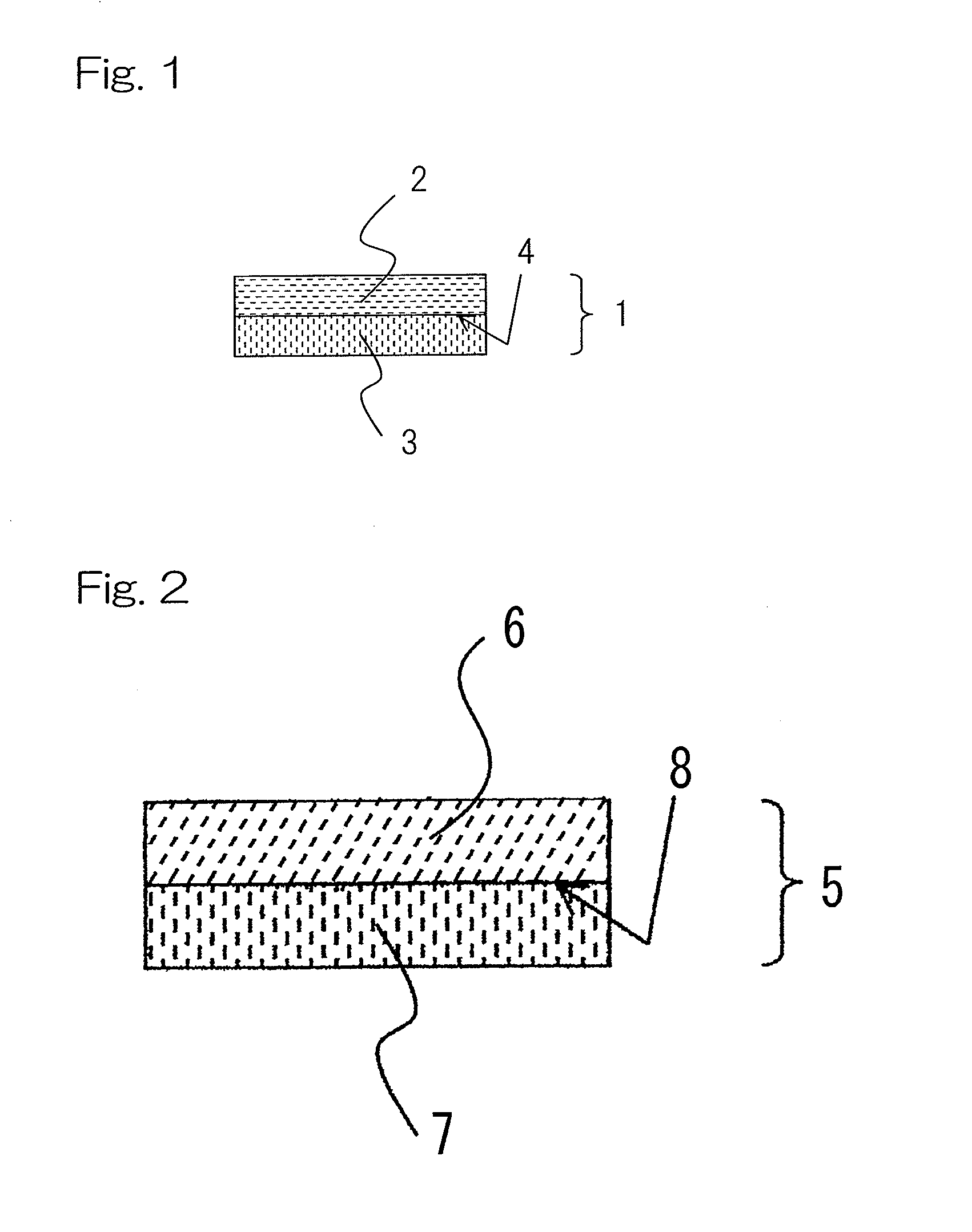
[0032]According to the first embodiment of the present invention, since the optical film laminate is obtained by laminating the positive C plate with the positive A plate, the optically biaxial plate, or the O plate to be directly bonded without adhesives, the optical film laminate can be used as a thinner optical compensation film. Because of the contact adhesion of the positive C plate with the positive A plate, the optically biaxial plate, or the O plate, without separating from each other, an optical compensation film can achieve high durability.
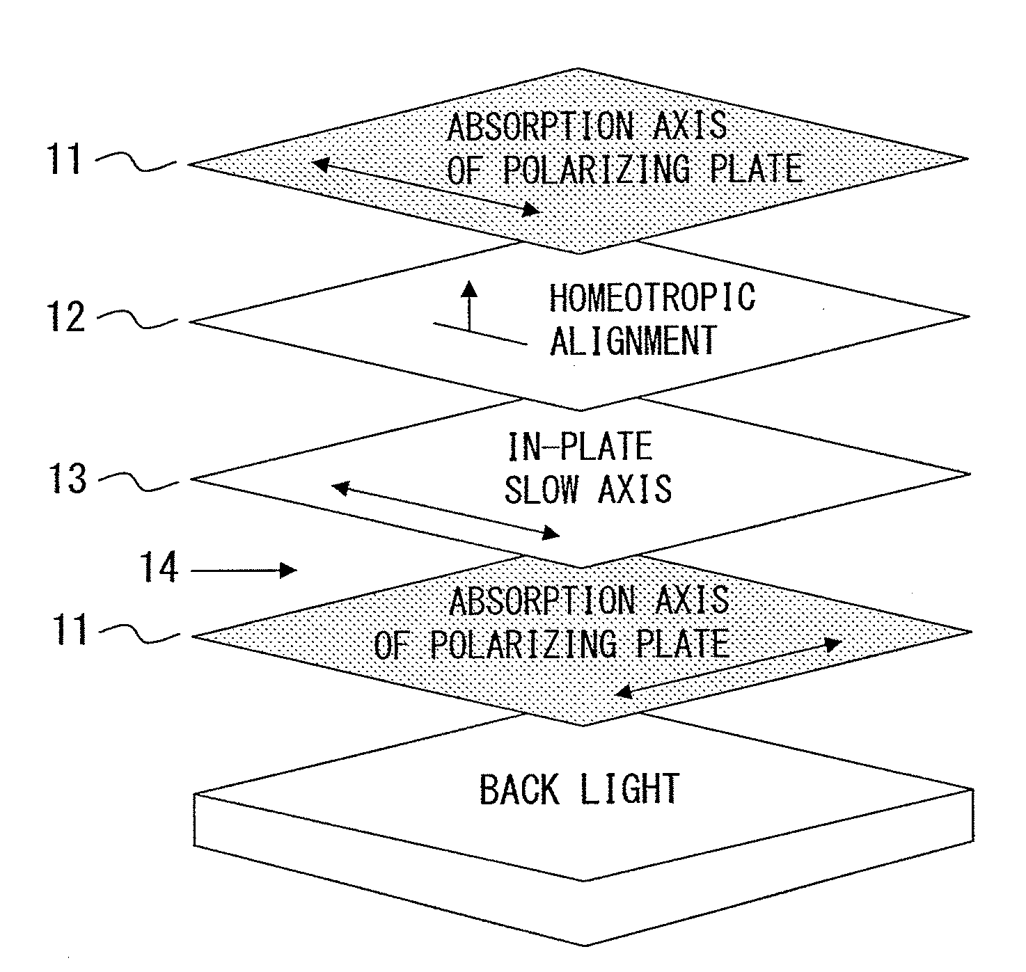
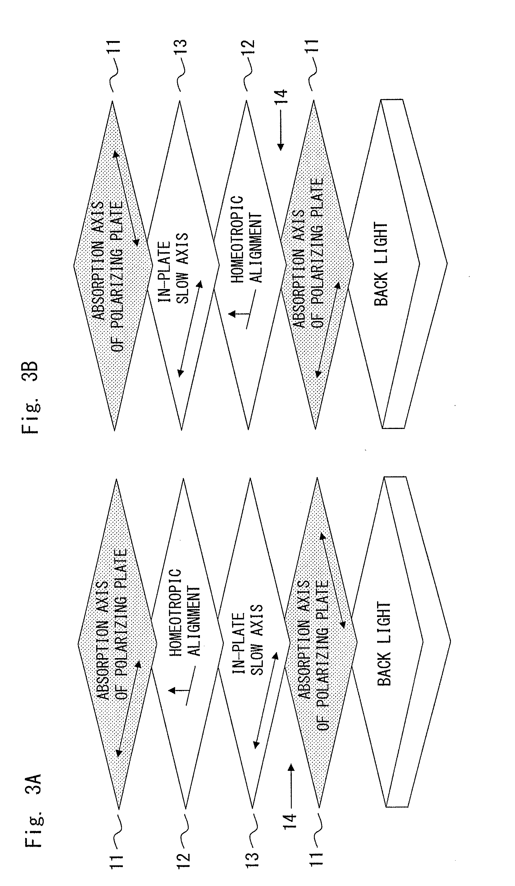
[0033]According to the second embodiment of the present invention, in the liquid crystal display panel comprising a polarizing plate and the above-mentioned optical film laminate, since the in-plane slow axis of the above-mentioned A plate, the optically biaxial plate, or the O plate is perpendicular or parallel to the absorption axis of the polarizing plate, transmitted light does not experience the phase difference when the liquid crystal display panel is viewed from front. The optical leakage can be decreased when viewed at an oblique angle through two polarizing plates crossing at right angle to each other.
[0034]According to the third embodiment of the present invention, since a positive A plate, an optically biaxial plate, or an O plate is bonded to a positive C plate without adhesive so as to provide an optical film laminate in which both layers is hardly separated from each other, a liquid crystal display with reduced thickness can be obtained. In such an embodiment, since lamination of a positive C plate to a positive A plate, an optically biaxial plate, or an O plate can be performed in a series of processes without adhesive, there is no contamination of foreign matter which is easy to adhere to an adhesive-applied surface. As a result, an efficient production line with a low product defect rate can be established.
[0035]According to the present invention, when both the photosensitive groups of materials A and B are a photosensitive group which reacts with each other when exposed to light, preferably when the photosensitive groups of both material A and material B are the same photosensitive group; the photosensitive groups of materials A and B tend to be bonded by the photo-reaction in the interface between the layer A and the layer B constituting both plates, so as to achieve a still firmer adherence configuration.

Problems solved by technology

Such an apparent absorption axis shift leads to a trouble that optical leakage is caused at the time of black display so as to reduce the contrast of the display.

Method used


Image

  • Optical film laminate, method for producing the same, and liquid crystal display panel using the same
  • Optical film laminate, method for producing the same, and liquid crystal display panel using the same
  • Optical film laminate, method for producing the same, and liquid crystal display panel using the same

Examples


example 1

[0125]The polymer 1 was dissolved in cyclohexanone, and thereto was added 4,4′-bis(diethylamino)benzophenone available from Tokyo Chemical Industry Co., Ltd. in the proportion of 0.02 part by weight relative to 1 part by weight of the polymer 1 to prepare a solution 1. The solution 1 was spin-coated at a thickness of about 1.5 μm onto a polyethylene terephthalate film (PET film). After drying the resultant material at a room temperature (about 25° C.), the material was heated to 100° C. followed by cooled to form a first coated layer. Next 4.2% by weight of the polymer 2 and 0.8% by weight of the low molecular material 1 were dissolved in toluene, and thereto was added 4,4′-bis(diethylamino)benzophenone available from Tokyo Chemical Industry Co., Ltd. in the proportion of 0.02 part by weight relative to 1 part by weight of the total amount of the polymer 2 and the low molecular material 1 to prepare a solution 2. The solution 2 was spin-coated at a thickness of about 1.8 μm onto the...

example 2

[0128]The polymer 3 was dissolved in 1,4-dioxane to prepare a solution 3. The solution 3 was spin-coated at a thickness of about 1.5 μm onto a polyethylene terephthalate film (PET film). After drying the resultant material at a room temperature (about 25° C.), the material was heated to 130° C. followed by cooled to form a first coated layer. Again the solution 3 was spin-coated at a thickness of about 2.0 μm onto the first coated layer and dried to form a second coated layer on the first coated layer. Here, without light irradiation to the first coated layer and without fixing its alignment (photosensitive groups are still un-reacted), the second coated layer was formed on the first coated layer.

[0129]Subsequently, light from a high pressure mercury vapor lamp is converted into a linear polarized light by using Gran-Taylor prism, and then the linear polarized light is irradiated to the coat layers for 300 seconds. The irradiated material is heated at 130° C., followed by gradually ...

example 3

[0137]In Example 1, without light irradiation to the first coated layer as well as without fixing its alignment (photosensitive groups are still un-reacted), a second coated layer is formed on the first coated layer. Thereafter, the coated layers were arranged at an inclined angle of 20° to a horizontal plane and irradiated with linear polarized light converted from light from a high pressure mercury vapor lamp for 300 seconds in the perpendicular direction to the horizontal plane (i.e., electric-field oscillating plane of light intersects perpendicularly to the tilt axis of the film). The irradiated material is heated at 100° C., followed by being cooled gradually for 30 minutes to the room temperature to induce the alignment. Further, light from a high pressure mercury vapor lamp is irradiated without converting into linear polarized light to the layers for 1,500 seconds in order to fix the alignment.

[0138]Thus obtained coated layers could be transferred from the PET support to a ...


PUM

PropertyMeasurementUnit
Photosensitivityaaaaaaaaaa

Abstract

Provided is an optical film laminate with a thinner thickness having an optical compensation function. According to the present invention is provided an optical film laminate comprising (i) a positive C plate comprising a liquid crystal material having a photosensitive group and (ii) a positive A plate, an optically biaxial plate, or an O plate, these plate comprising a liquid crystal material having a photosensitive group; wherein the both plates are directly bonded with each other to be firmly laminated without adhesive.

Description

CROSS REFERENCE TO THE RELATED APPLICATIONS[0001]This application is based on and claims Convention priority to Japanese patent applications No. 2011-129107 and No. 2011-186395, filed Jun. 9, 2011 and Aug. 29, 2011, respectively, the entire disclosures of which are herein incorporated by reference as a part of this application.FIELD OF THE INVENTION[0002]This invention relates to an optical film laminate used for a liquid crystal display, a method for producing the same, and a liquid crystal display panel using the same, and in particular, relates to an optical film laminate having an optical compensation function to improve viewing angle characteristics of the liquid crystal display, a method for producing the same, and a liquid crystal display panel using the same.BACKGROUND ART[0003]Liquid crystal displays are required for having a wider viewing angle as well as a higher contrast ratio. Liquid crystal displays (LCDs) of IPS (In-plane Switching: IPS) mode are mentioned as such a l...

Claims


Application Information

Patent Timeline
IPC IPC(8): G02F1/13363G02B1/08B05D5/06G02B1/10
CPCG02F1/13363G02F1/133632G02F1/133634G02F2413/06G02F2001/133726G02F2202/023G02F2413/02G02F2001/133633G02F1/133633G02F1/133726G02B5/30G02F1/1335
Inventor SAKAI, TAKEYA
Owner HAYASHI TELEMPU CO LTD
Learn More