Speaker system and method of operation therefor

Inactive Publication Date: 2012-12-27
KONINKLIJKE PHILIPS ELECTRONICS NV
View PDF6 Cites 19 Cited by
  • Summary
  • Abstract
  • Description
  • Claims
  • Application Information

AI Technical Summary

Benefits of technology

[0034]This may in many embodiments provide an improved performance. In particular, an advantageous trade-off between audio quality and spatial perception may be achieved. In some embodiments, the higher 3 dB cut-off frequency may advantageously be no less than 600 Hz, 700 Hz or 800 Hz.
[003

Problems solved by technology

However, a problem with conventional surround sound systems is that they require a high number of separate speakers located at specific positions.
The high number of speakers not only increases cost but also results in reduced practicality and increased inconvenience to users.
In particular, it is generally considered a disadvantage that loudspeakers at specific positions in front as well as to the rear of listeners are needed.
The rear loudspeakers are particularly problematic due to the required wiring and the physical impact they impose on the interior of the room.
However, such approaches of providing virtual sound sources tend to be less robust than real sources positioned to the rear of the listener and tend to provide reduced audio quality and a reduced spatial experience.
Indeed, it is often difficult to accurately direct audio signals to provide the desired reflections that achieve the desired virtual sound source position.
Furthermore,

Method used


Image

  • Speaker system and method of operation therefor
  • Speaker system and method of operation therefor
  • Speaker system and method of operation therefor

Examples


Embodiment Construction

[0062]The following description focuses on embodiments of the invention applicable to a surround sound system and in particular to a system with five spatial channels. However, it will be appreciated that the invention is not limited to this application but may be applied to many other audio reproduction systems including for example a single audio channel system.

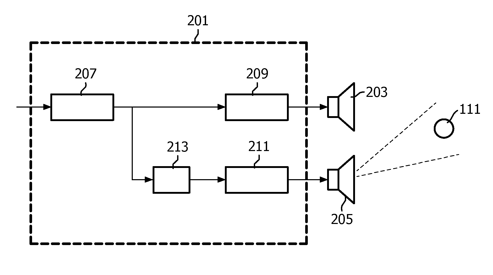
[0063]FIG. 1 illustrates a speaker system setup in a conventional five channel surround sound system, such as a home cinema system. The system comprises a center speaker 101 providing a center front channel, a left front speaker 103 providing a left front channel, a right front speaker 105 providing a right front channel, a left rear speaker 107 providing a left rear channel, and a right rear speaker 109 providing a right rear channel. The five speakers 101-109 together provide a spatial sound experience at a listening position 111 and allow a listener at this location to experience a surrounding and immersive sound experie...


PUM


Abstract

A speaker system comprises a first speaker (203) and a second speaker (205). A driving circuit receives an audio signal and comprises a first drive circuit (209) generating a first drive signal for the first speaker (203) in response to a first filtering of the audio signal with a first pass band. A second drive circuit (211) generates a second drive signal for the second speaker (205) in response to a second filtering having a second pass band which comprises a frequency band below the first pass band. A delay (213) delays the second drive signal relative to the first drive signal. The sound from the second speaker is directionally radiated with a directional radiation pattern having a notch towards the listening position (111). The system uses the precedence effect and non-direct low frequency audio radiation to ensure that directional cues are predominantly provided by the first speaker (203) which may be small and positioned remote from the second speaker (205).

Description

FIELD OF THE INVENTION[0001]The invention relates to a speaker system and method of operation therefor and in particular, but not exclusively, to a speaker system for a rear channel of a surround sound system.BACKGROUND OF THE INVENTION[0002]In recent years, spatial sound provision has become increasingly popular such as e.g. evidenced by the wide popularity of various surround sounds systems. For example, the increased popularity of home cinema systems has resulted in a surround sound systems being common in many private homes. However, a problem with conventional surround sound systems is that they require a high number of separate speakers located at specific positions.[0003]For example, a conventional Dolby 5.1 surround sound system requires right and left rear speakers, as well front centre, right and left speakers. In addition, a low frequency subwoofer may be used.[0004]The high number of speakers not only increases cost but also results in reduced practicality and increased ...

Claims


Application Information

Patent Timeline
IPC IPC(8): H03G5/00H04R5/02
CPCH04R1/323H04R3/12H04R2203/12H04R2217/03H04S2420/07H04R2499/15H04S7/302H04S2420/05H04R2430/25
Inventor DE BRUIJN, WERNER PAULUS JOSEPHUSLAMB, WILLIAM JOHN
Owner KONINKLIJKE PHILIPS ELECTRONICS NV
Why Eureka
Try Eureka