Multi-well plate with filter medium, and use thereof

a filter medium and multi-well technology, applied in the field of multi-well plates, can solve the problems of unsuitable devices for parallel screening of a plurality of samples, unoptimized fluid discharge from cylindrical wells, and inability to carry out individual tests, etc., to achieve rapid and inexpensive production, promote undesired radial cross-diffusion of analytes, and high flow rate

Inactive Publication Date: 2012-12-27
SARTORIUS STEDIM BIOTECH GMBH
View PDF4 Cites 12 Cited by
  • Summary
  • Abstract
  • Description
  • Claims
  • Application Information

AI Technical Summary

Benefits of technology

[0031]Alternatively, the sealing means can be annular sealing beads which are milled out on the sides of the lower part and of the upper part facing toward the filter medium. This embodiment permits rapid and inexpensive production of the upper part and lower part from monolithic (one-piece) blanks, into which the multiplicity of wells can be introduced, in which case the elevations of the sealing beads extending around the wells can be milled out from the blank.
[0032]Surprisingly, it has been found to be particularly advantageous if the filter medium fixed between upper part and lower part can be fixed by respective pairs of the sealing means of the upper part and lower part. This ensures that the filter medium, on the permeate side thereof, does not lie across its entire surface on the side of the lower part facing toward the filter medium, which would promote undesired radial cross-diffusion of analytes.
[0033]In order to avoid cross-contamination between adjacent wells, while at the same time ensuring a high rate of flow of filtered fluid through the multi-hole plate according to the invention, it has proven useful, in a particularly preferred embodiment, if the multiplicity of wells in the upper part are cylindrical channels with a diameter d1, and the multiplicity of wells arranged in the lower part, and communicating with these cylindrical channels, have a transition area on their side facing toward the filter medium, which transition area narrows from the diameter d1 to a diameter d2, and, on the side of the lower part facing away from the filter medium, the transition area is adjoined in each case by a cylindrical channel with the diameter d2.
[0034]Optimal results in terms of avoiding cross-contamination, while at the same time ensuring a very high rate of flow of fluid through the multi-well plate, are achieved if the ratio between the aforementioned diameters d1 and d2 is at least 4.0, preferably at least 6.6 and particularly preferably at least 8.0.

Problems solved by technology

Especially for optimization in the elaboration of biotechnology products, it is not practicable to carry out individual tests to examine the influence of media properties (nature and composition) or the interaction of proteins with other compounds.
Since only one medium can be filtered with one device, this device is unsuitable for parallel screening of a plurality of samples.
As far as undesired cross-contamination between adjacent wells is concerned, the non-optimized fluid discharge from the cylindrical wells, which is possible only with application of a vacuum, and the cross-diffusion on the filter paper are problematic, because the multi-well plate has no sealing means between upper part and lower part for ensuring individual sealing of the individual wells in the upper part.
The use of an adhesive as sealant is unacceptable for many biotechnology applications because of the possible contamination of the filtrate by dissolved components of the adhesive.
Moreover, replacement of the filter sheet in the filter plate is not possible.
The outlets of the individual wells are so narrow that no flow is possible by gravity alone, and the drops of the filtrate that form and remain at the outlet can produce an undesired cross-mixing between adjacent wells.
However, a great disadvantage of this device is that each individual hole is equipped with an individual membrane cutout.
Furthermore, a uniform flow through the membrane cutouts is not ensured, because the membrane cutouts lie partially on the well bottom on the permeate side.
Similar disadvantages also arise for other commercially available plates (“Filter Bottom Microplates” from Seahorse Bioscience) for screening applications.
The outflow and the sealing of the wells are not designed for membrane adsorbers.
Apart from the fact that the separated membrane sections cannot easily be removed from the multi-well plate for further analysis after the filtration, the aforementioned welding has an adverse effect on membrane materials with low thermal loading capacity, e.g. materials based on polysaccharides, such that the filtration properties of the membrane sections may be impaired in the edge areas of the membrane sections lying adjacent to the seal that has been produced by welding.
This device has in principle proven to be excellent for the aforementioned methods but has the disadvantage that, because of the inadequate sealing of the individual wells and the plane construction of the support surface for the filter sheet in the lower part (“holding tray”), it is unsuitable for filtration processes which involve separation of substances by adsorption and in which (bio)chemical binding reactions have to be quantitatively balanced.
When a stack of several membrane adsorber sheets is used in a multi-well plate according to U.S. Pat. No. 5,939,024 for separation of substances by adsorption, undesired cross-contamination is observed between the individual wells as a result of radial cross-diffusion beyond the individual well, which is sealed off only by the annular bulges on the upper part.
When a stack of several membrane adsorber sheets is used as filter medium, the sealing means proposed in U.S. Pat. No. 5,939,024 are not sufficient to exclude the possibility of cross-contamination between adjacent wells.
This undesired spread of analytes beyond the peripheral well boundaries causes balancing errors in respect of the adsorption of the analyte per membrane surface, e.g. in binding studies.

Method used


Image

  • Multi-well plate with filter medium, and use thereof
  • Multi-well plate with filter medium, and use thereof
  • Multi-well plate with filter medium, and use thereof

Examples


example 1

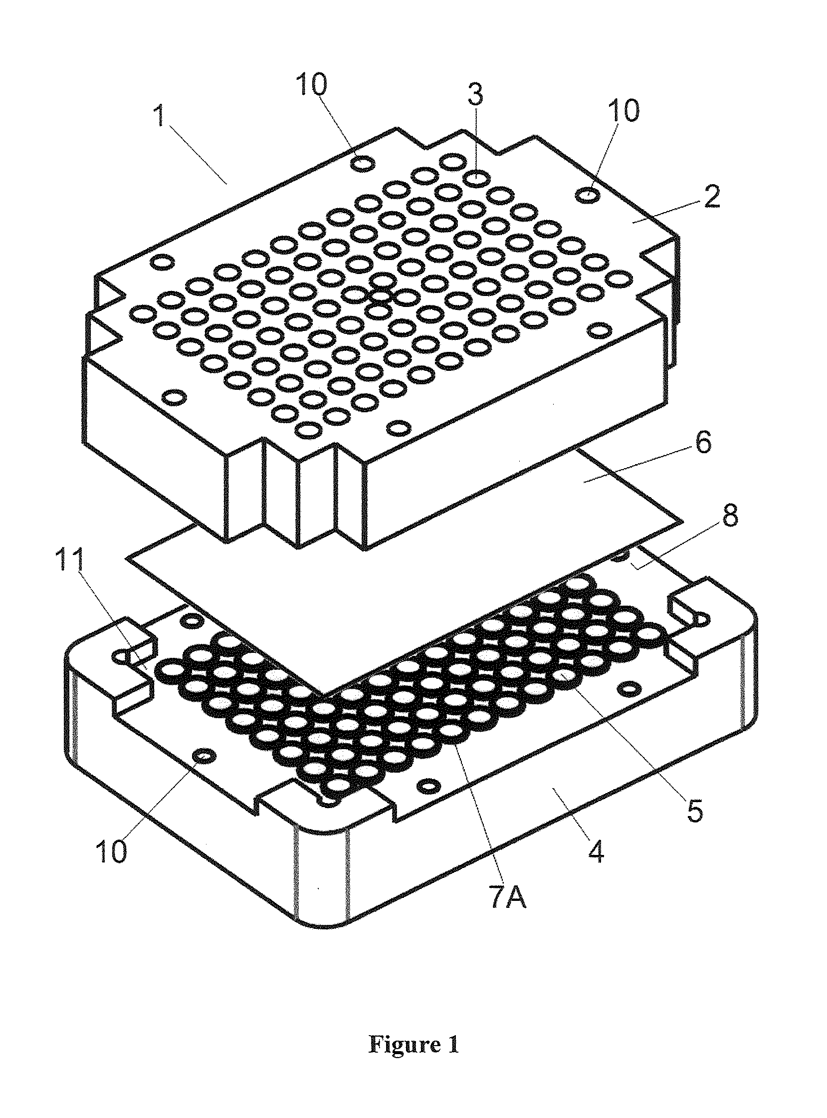
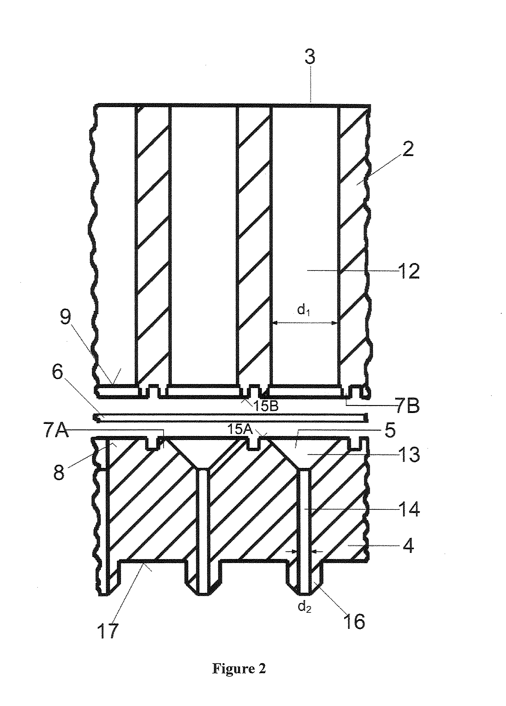
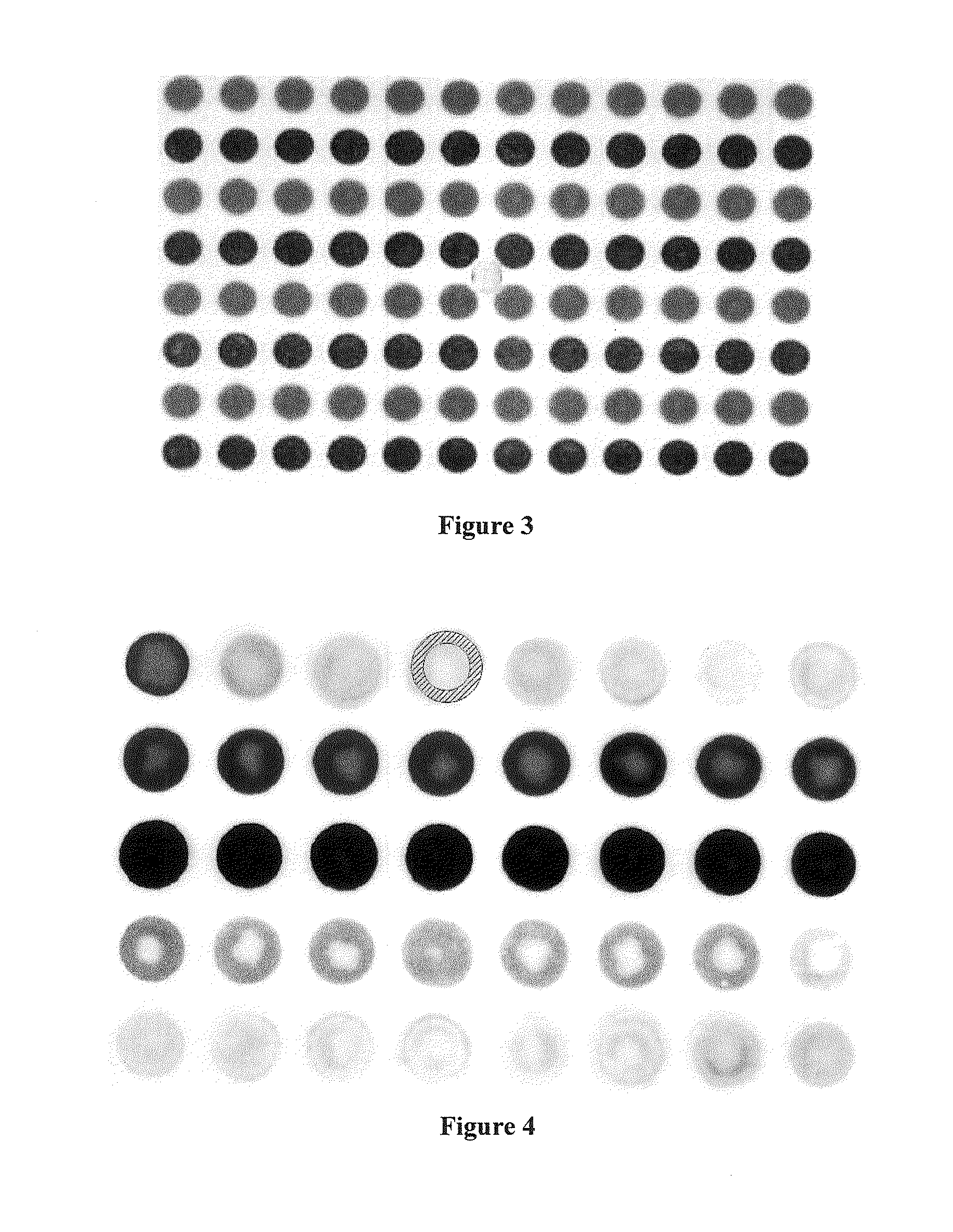
[0064]Detection of the suppression of cross-contamination between adjacent reaction spaces of the multi-well plate 1 according to the invention with sealing means 7a and 7b arranged in pairs on the upper part and lower part

[0065]Dye tests are carried out to detect how the individual sections of the filter medium 6 enclosed in the reaction spaces are sealed off by the sealing means 7a and 7b in respect of binding substances. The filtration medium 6 consists of three sheets of a microporous cellulose membrane (surface area per sheet: 86 cm2, thickness of each sheet 250 μm) with quaternary ammonium groups as anion-exchanging groups (Sartobind® Q Membrane from Sartorius Stedim Biotech GmbH) and, after wetting by RO (reverse osmosis) water, is placed in the receiving area 11 of the lower part 4. After it has been screwed together with the upper part 2, the lower part 4 is positioned on a vacuum-generating suction device. The reaction spaces of the assembled multi-well plate 1 are filled,...

example 2

[0071]Detection of the exclusion of cross-contamination between adjacent reaction spaces by means of the phosphate test according to Cooper

[0072]A multi-well plate 1 according to the invention, as shown in FIGS. 1 and 2, is preferably used for applications in the field of high-throughput screening, in which different charging conditions in respect of the buffer composition occur in the individual wells. A precondition for this is that the salts contained in the buffer solutions also cannot pass from one well to an adjacent well by radial cross-diffusion. To detect that inorganic salt solutions in the wells also do not cause cross-contamination, the multi-well plate 1 is equipped with three sheets of an ion exchange membrane from Example 1, pre-wetted with RO water, and is then wetted column by column with 0.5 ml phosphate solution NaH2PO4 at a concentration of 0.16 g / l per well. All other wells are filled with distilled water. After 15 minutes the liquids are conveyed by a pressure ...

example 3

[0074]Recording breakthrough curves in the high throughput method with the multi-well plate according to the invention

[0075]Breakthrough curves of membranes are generally plotted by the continuous charging of filtration units. They show whether and to what extent a membrane is able to bind or hold back one or more substances. Depending on the surface area of the membrane used, the most expensive substances often have to be applied in a large quantity. Therefore, for economic reasons, simultaneous multiple tests cannot be carried out.

[0076]The multi-well plate according to the invention allows a breakthrough curve to be recorded with minimal use of analytes. A protein solution is introduced into individual wells at a constant concentration, but in different volumes. When the charge concentration is known, the breakthrough can be recorded and assessed by analysis of the permeate. For technical purposes, it is often sufficient to detect when a breakthrough of at most 10% of the protein...


PUM

PropertyMeasurementUnit
surface areaaaaaaaaaaa
concentrationaaaaaaaaaa

Abstract

A multi-well plate (1) has an upper part (2) with a multiplicity of wells (3), a lower part (4) with a multiplicity of wells (5) that communicate with the wells (3) of the upper part (2), and at least one filter medium (6) that can be fixed between the upper and lower parts (2, 4). Sides (8, 9) of the upper and lower parts (2, 4), facing toward the filter medium (6), have seals (7a, 7b) extending around the wells. The filter medium (6) can be fixed along the upper and lower sides in each case by pairs of the seals (7b) of the upper part (2) and the seals (7a) of the lower part (4). The multi-well plate prevents cross-contamination between adjacent wells due to radial cross-diffusion of analytes. A method for characterization of filter media using the multi-well plate (1) also is provided.

Description

BACKGROUND OF THE INVENTION[0001]1. Field of the Invention[0002]The present invention relates to a multi-well plate with an upper part and a lower part, each having a multiplicity of communicating wells, and with a filter medium, which can be fixed between the upper part and the lower part by sealing means, and to the use thereof for high throughput analyses for characterization of membranes for separation of substances by adsorption.[0003]2. Description of the Related Art[0004]For characterization of membranes for separation of substances by adsorption, many parameters have to be examined. Especially for optimization in the elaboration of biotechnology products, it is not practicable to carry out individual tests to examine the influence of media properties (nature and composition) or the interaction of proteins with other compounds. High throughput screening systems (HTS systems) or multi-well systems are increasingly being used, with which it is possible to test a large number of...

Claims


Application Information

Patent Timeline
Patent Type & Authority Applications(United States)
IPC IPC(8): G01N1/34G01N33/68G01N21/75
CPCB01D63/082B01L2400/049B01L2300/0829B01L2200/0631B01D63/087B01L3/50255B01L2200/141B01D65/003B01D61/18B01D2313/025B01L2200/0689
Inventor FABER, RENELEUTHOLD, MARTIN
Owner SARTORIUS STEDIM BIOTECH GMBH
Why Eureka
Try Eureka