Bone cement injection puncture needle

Inactive Publication Date: 2012-12-27
ST MARIANNA UNIV SCHOOL OF MEDICINE +1
View PDF5 Cites 14 Cited by
  • Summary
  • Abstract
  • Description
  • Claims
  • Application Information

AI Technical Summary

Benefits of technology

[0016]With the above arrangement, a step between the distal end portion of the inner tube and the distal end portion of the outer needle serves as a marker that is used when carrying out image guidance (X-ray fluoroscopy or CT fluoroscopy). Since the step can visually be recognized easily in the image, the outer needle can be inserted simply and reliably into the bone. Since bone cement, which has flowed out from the distal end of the inner tube does not become adhered to

Problems solved by technology

However, puncture needles that have heretofore been used are disadvantageous in that when bone cement is injected by the single-needle method, the bone cement may possibly leak out from the bone.
More specifically, when bone cement is injected by t

Method used


Image

  • Bone cement injection puncture needle
  • Bone cement injection puncture needle
  • Bone cement injection puncture needle

Examples


Example

First Embodiment

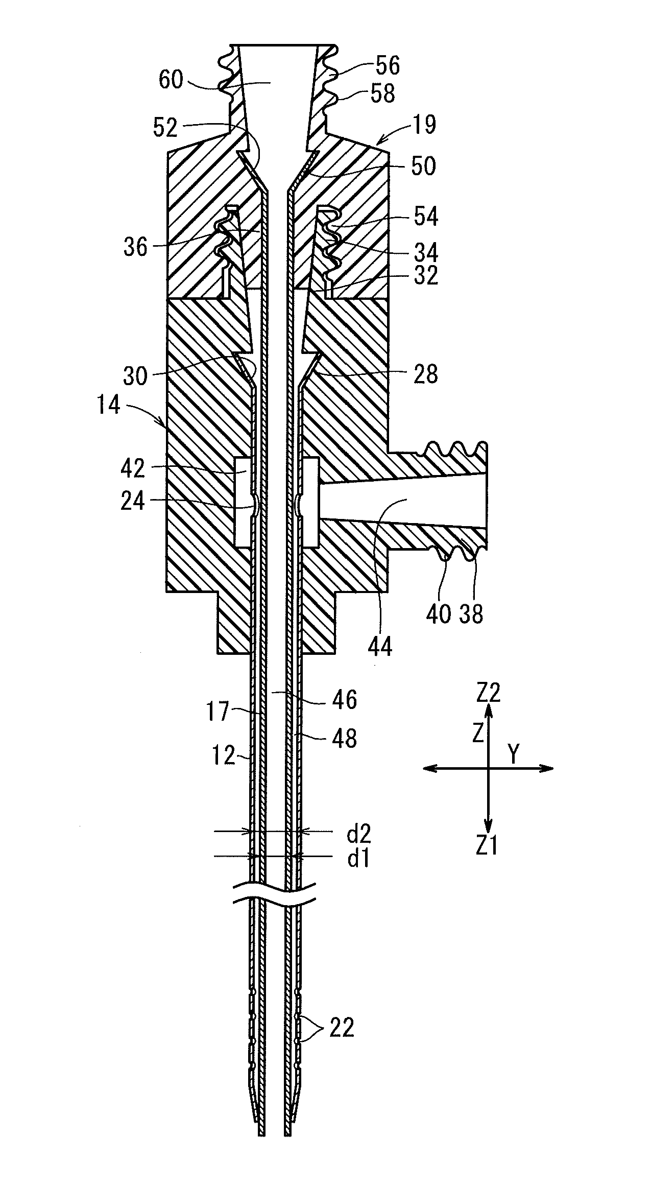
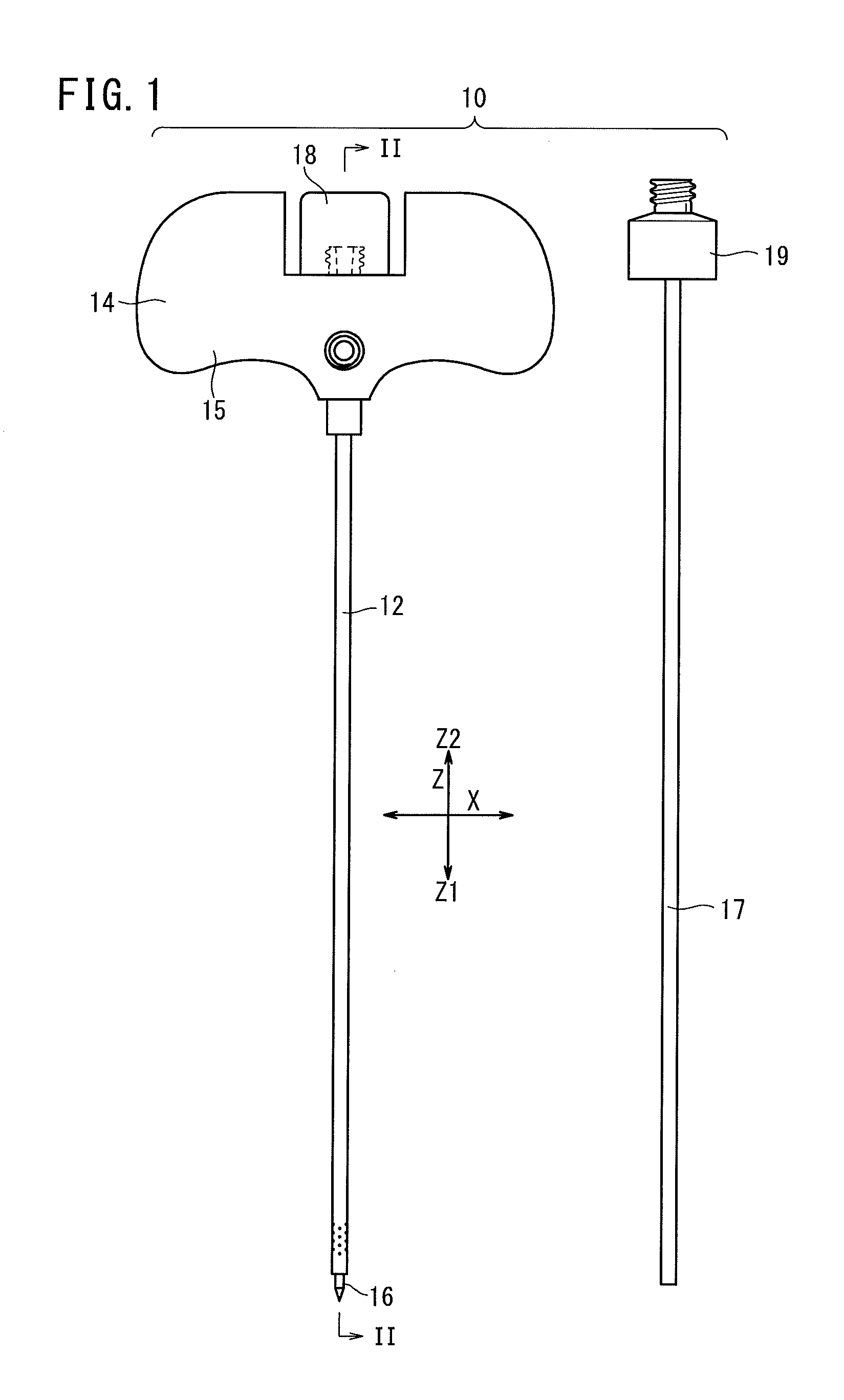
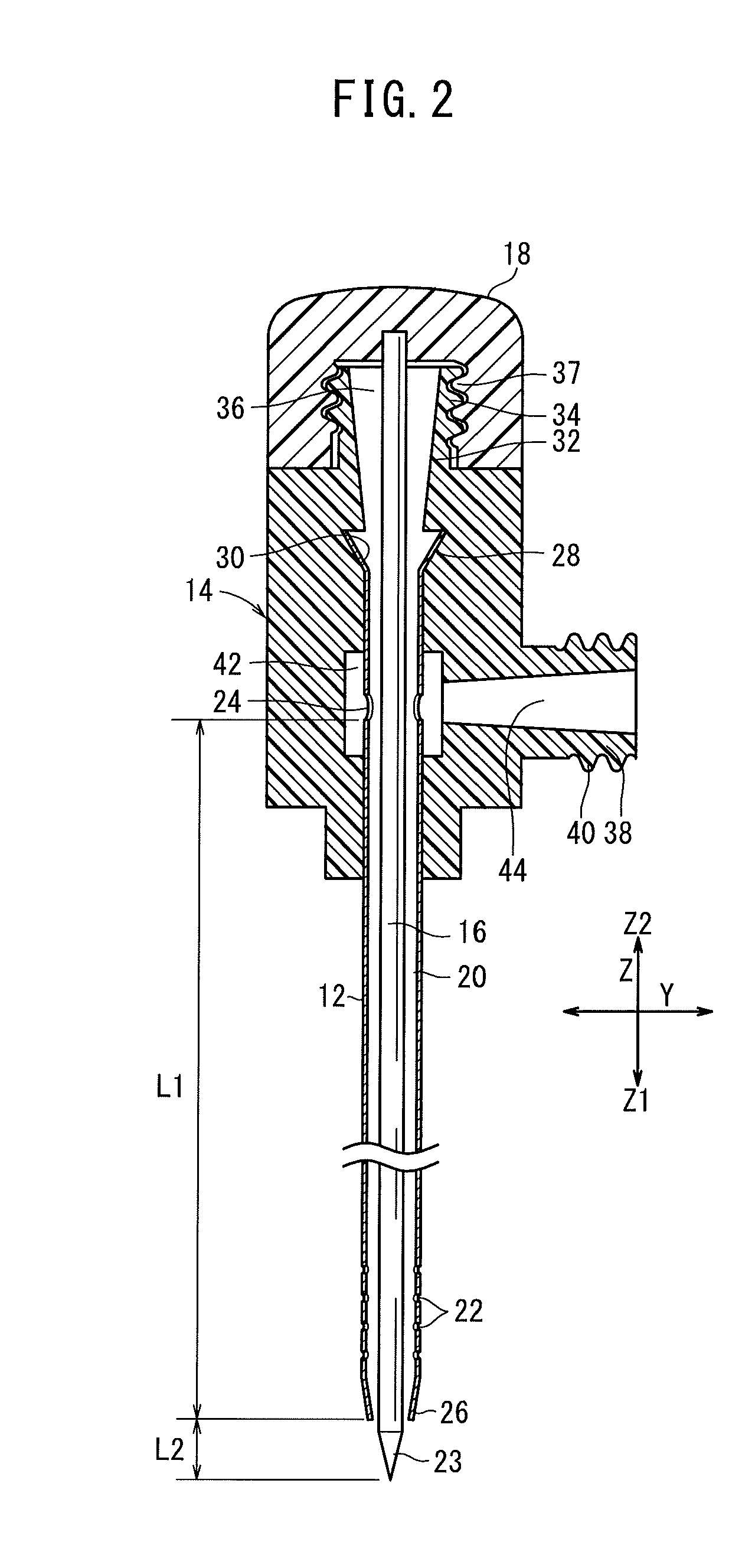
[0040]FIG. 1 is an overall view of a bone cement injection puncture needle 10 (hereinafter referred to as a “puncture needle 10”) according to a first embodiment of the present invention. As shown in FIG. 1, the puncture needle 10 comprises an outer needle 12 having hollow constitution, an outer needle hub 14 fixed to a proximal end portion of the outer needle 12, an inner needle 16 which is insertable in the lumen in the outer needle 12, an inner needle hub 18 fixed to a proximal end portion of the inner needle 16, an inner tube 17 which is insertable in the lumen in the outer needle 12, and an inner tube hub 19 fixed to a proximal end portion of the inner tube 17. In FIG. 1, the inner needle 16 is shown as being inserted into the outer needle 12, while the inner tube 17 is shown as being removed from the outer needle 12.

[0041]In the following description, axial directions of the inner needle 16 and the outer needle 12 are referred to as Z directions, directions per...

Example

Second Embodiment

[0087]FIG. 7 is a cross-sectional view, partially omitted from illustration, of a bone cement injection puncture needle 10a (hereinafter referred to as a “puncture needle 10a”) according to a second embodiment of the present invention. Parts of the puncture needle 10a according to the second embodiment, which function identically and have the same advantages as those of the puncture needle 10 according to the first embodiment, are denoted by identical reference characters, and such features will not be described in detail below.

[0088]The puncture needle 10a according to the second embodiment includes an outer needle 12a, which replaces the outer needle 12 of the puncture needle 10 according to the first embodiment, and wherein the outer needle 12a is different in constitution from the outer needle 12. The outer needle 12a has a flaring portion 28a and side holes (proximal-end holes) 24a, which are constitutively identical to the flaring portion 28 and the second sid...

Example

Third Embodiment

[0105]FIG. 12 is a cross-sectional view, partially omitted from illustration, of a bone cement injection puncture needle 10b (hereinafter referred to as a “puncture needle 10b”) according to a third embodiment of the present invention. Parts of the puncture needle 10b according to the third embodiment, which function identically and have the same advantages as those of the puncture needle 10 according to the first embodiment, are denoted by identical reference characters, and such features will not be described in detail below.

[0106]According to the first and second embodiments, as described above, the grip 15, which is gripped by the user of the puncture needles 10, 10a, is included on the outer needle hub 14 (see FIG. 1). According to the third embodiment, however, a different grip 76, which extends in directions perpendicular to the axis of the inner needle 16, is included on an inner needle hub 18a, and the outer needle hub 14b does not include any constitution t...


PUM


Abstract

An outer needle of a bone cement injection puncture needle has first side holes near the tip, and second side holes near the base. When an inner needle is removed from the outer needle and an inner tube is inserted into the outer needle in place thereof, a reduced-pressure passage is formed between the outer needle and the inner tube. When bone cement is injected into a bone, gas and liquid in the bone pass through the reduced-pressure passage and are discharged from the body, thereby preventing increased pressure in the bone. As a result, the bone cement can be prevented from leaking to outside of the bone.

Description

TECHNICAL FIELD[0001]The present invention relates to a puncture needle for injecting bone cement into a bone.BACKGROUND ART[0002]Percutaneous vertebroplasty is a therapeutic method which is used to alleviate pain caused by a compression fracture of a vertebral body of the patient by injecting bone cement into the injured area of the vertebral body to reinforce the vertebral body. Percutaneous vertebroplasty is a relatively new treatment technique that was first performed in France in 1987, and is now conducted in many medical facilities throughout Japan.[0003]Basically, percutaneous vertebroplasty is based on a transpedicular approach, wherein a hollow puncture needle is inserted into a vertebral body through the pedicle that lies horizontally on the back of the vertebral body, and bone cement is injected into the vertebral body through a passage in the hollow puncture. Generally, a bone biopsy needle is used as the puncture needle for injecting bone cement. For details, see Japane...

Claims


Application Information

Patent Timeline
IPC IPC(8): A61B17/56
CPCA61B17/8816A61B17/8827A61B17/8819A61B17/34A61B17/56A61F2/28A61M5/158A61M2005/1587
Inventor TAKIZAWA, KENJIHAYAKAWA, KOICHI
Owner ST MARIANNA UNIV SCHOOL OF MEDICINE
Why Eureka
Try Eureka