Specimen box for electron microscope

a technology of electron microscope and specimen box, which is applied in the field of specimen boxes, can solve the problems of inability to observe specimen stimuli under the conventional electron microscope, inability to select specimens, invalidation of conventional electron microscope selection, etc., and achieve the effect of prolonging the in-situ observation time effectively

Active Publication Date: 2013-01-10
NAT CHIAO TUNG UNIV
View PDF0 Cites 5 Cited by
  • Summary
  • Abstract
  • Description
  • Claims
  • Application Information

AI Technical Summary

Benefits of technology

[0010]The object of the present invention is to provide a specimen box for an electron microscope, in which the specimen box comprises through holes and plugs. Hence, the specimen box can be reopened to inject gas or liquid again so as to prolong the in-situ observation time effectively.

Problems solved by technology

Hence, the conventional electron microscope has a limitation on the selection of specimens and is invalid for the dynamic observation of specimens.
Even the stimuli-induced responses of specimens are unobservable under the conventional electron microscope.
Due to the above-mentioned limitations, the application of the electron microscope is restricted.
However, the vacuum degree of the electron microscope may be degraded due to the easy evaporation of liquid from the specimen into the vacuum environment through the sealant or the polymer sealant.
However, the inert gas filled in the gas chamber for the pressure equilibrium may affect the observation resolution.
In addition, the structure of this specimen box is complicated so the cost is increased.
Due to finite oxygen contained in the closed space, the long-term dynamic changes and the light- or current-induced responses of the specimens cannot be observed under the electron microscope and thus the observation of living tissues or cells is limited.

Method used


Image

  • Specimen box for electron microscope
  • Specimen box for electron microscope
  • Specimen box for electron microscope

Examples


example 1

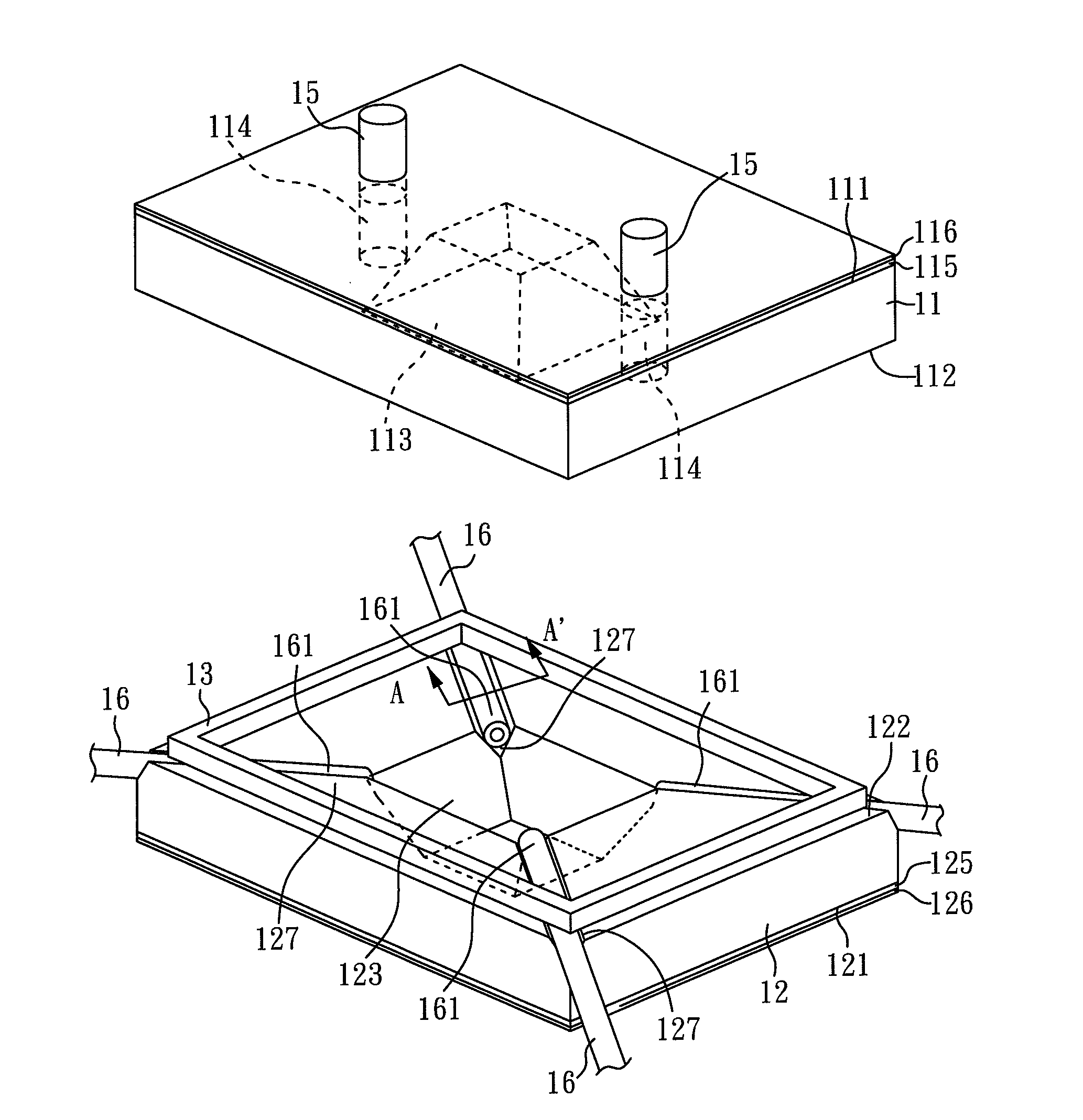
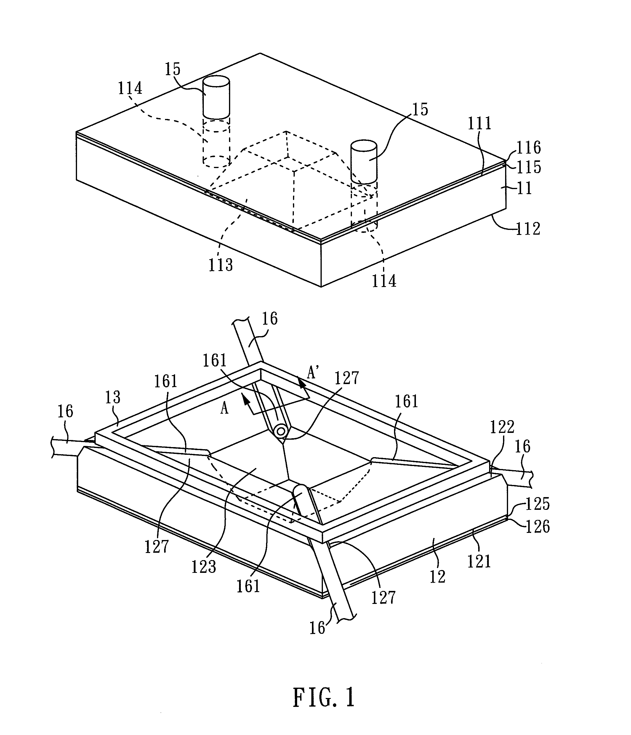
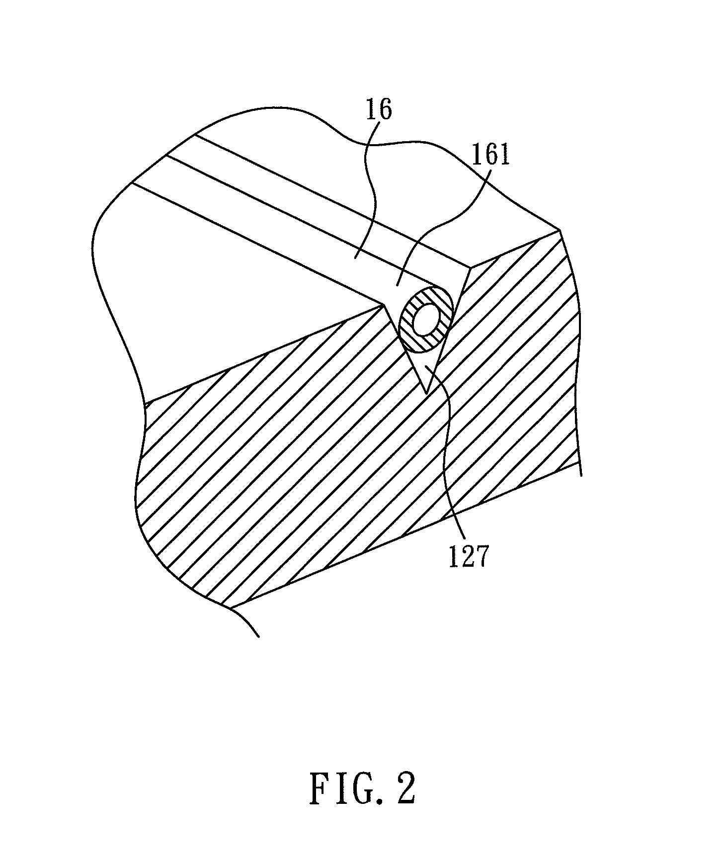
[0031]As showing in FIG. 1, FIG. 2, and FIG. 3, FIG. 1 a three-dimensional view showing the specimen box for electron microscope of the example 1; FIG. 2 is a three-dimensional view showing the photoelectric element of the specimen box for an electron microscope; and FIG. 3 is a three-dimensional view, which is shown along the A-A′ section line in FIG. 1, showing the specimen box for an electron microscope of the example 1. According to FIG. 1, FIG. 2, and FIG. 3, the specimen box of the present invention comprises: a first substrate 11, a second substrate 12, a metal adhesion layer 13, and four photoelectric elements 16. In the present example, the first substrate 11 and the second substrate 12 are (001) silicon substrate. The thickness of the first substrate 11 is 250 μm, and the thickness of the second substrate 12 is also 250 μm.

[0032]The first substrate 11 has a first surface 111, a second surface 112, a first concave 113, and two first through holes 114, in which the first con...

example 2

[0045]FIG. 4 is a perspective view showing the specimen box for an electron microscope of the example 2. According to FIG. 4, the specimen box of the present example is roughly the same as example 1. The only difference is the disposition of the metal adhesion layer 13. In the present example, the metal adhesion layer 13 is disposed between the second surface 112 and the second protective layer 126. Four of the third concaves 117 are formed on the second surface 112 of the first substrate 11 by a dry etching process. The photoelectric element 16, which is disposed on the third concave 117, is an optical fiber, an electrode, or the combination thereof.[0046]The volume of the space (not shown) in the present example is 2 mm3. The height of the space (not shown) is 550 μm. In the present example, the volume of the space (not shown) is smaller than example 1, so the resolution is higher than example 1. Therefore, different volumes of the space (not shown) of the specimen box could be ch...

example 3

[0047]FIG. 5 is a perspective view showing the specimen box for an electron microscope of the example 3. According to the FIG. 5, the specimen box of present example is roughly the same as example 1. The only difference in the present example is the first thin film 115, the first protective layer 116, the second thin film 125, and the second protective layer 126 are only disposed on the first concave 113 and the second concave 123 to enhance the structure of the first concave 113 and the second concave 123. Therefore, the first thin film 115 and the second thin film 125 would not be cracked so as to avoid the specimen escaping from the space (not shown).

[0048]A fourth concave 127 is formed on the second surface 122 of the second substrate 12 by a wet etching process. The photoelectric element 16 is disposed on the fourth concave 127, in which the photoelectric element 16 is an optical fiber, an electrode, or a combination thereof.

[0049]In addition, the first through holes 114 and th...


PUM


Abstract

The present invention relates to a specimen box for an electron microscope, comprising a first substrate, a second substrate, one or more photoelectric elements, and a metal adhesion layer. The first substrate has a first surface, a second surface, a first concave, and one or more first through holes, wherein the first through holes penetrate through the first substrate. The second substrate has a third surface, a forth surface, and a second concave. The photoelectric element is disposed between the first substrate and the second substrate. In addition, the metal adhesion layer is disposed between the first substrate and the second substrate to form a space for a specimen contained therein. Besides, the present specimen box further comprises one or more plugs. When the plugs are assembled into the first through holes to seal the specimen box, the in-situ observation can be accomplished by using the electron microscope.

Description

CROSS REFERENCE TO RELATED APPLICATION[0001]This application claims the benefits of the Taiwan Patent Application Serial Number 100123732, filed on Jul. 5, 2011, the subject matter of which is incorporated herein by reference.BACKGROUND OF THE INVENTION[0002]1. Field of the Invention[0003]The present invention relates to specimen box with one or more through holes for use with an electron microscope, especially to a specimen box with one or more photoelectric elements for use with an electron microscope.[0004]2. Description of Related Art[0005]As known in the prior art, a vacuum environment inside an electron microscope is critical for high resolution and accuracy during the observation of specimens under the electron microscope. Considering the vacuum environment, the conventional electron microscope is usually used to observe the structures of solid substances or specimens, such as dehydrated bio-tissueor dehydrated virus. Hence, the conventional electron microscope has a limitati...

Claims


Application Information

Patent Timeline
Patent Type & Authority Applications(United States)
IPC IPC(8): H01J37/16
CPCH01J2237/2003H01J37/20
Inventor CHEN, CHIHTU, KING-NING
Owner NAT CHIAO TUNG UNIV
Why Eureka
Try Eureka