
Electrospinning apparatus for producing nanofibres and capable of adjusting the temperature and humidity of a spinning zone

a technology of electropinning apparatus and nanofibers, which is applied in the direction of dough shaping, manufacturing tools, food shaping, etc., can solve the problems of destabilizing the solidification speed of nanofibers, reducing the volatilization speed of solvents, and affecting the cleanliness of products, so as to facilitate volatilization and discharge of solvents, uniform and small diameters, and uniform diameters

Inactive Publication Date: 2013-01-10
FIBRANE
View PDF4 Cites 17 Cited by
  • Summary
  • Abstract
  • Description
  • Claims
  • Application Information

AI Technical Summary

Benefits of technology

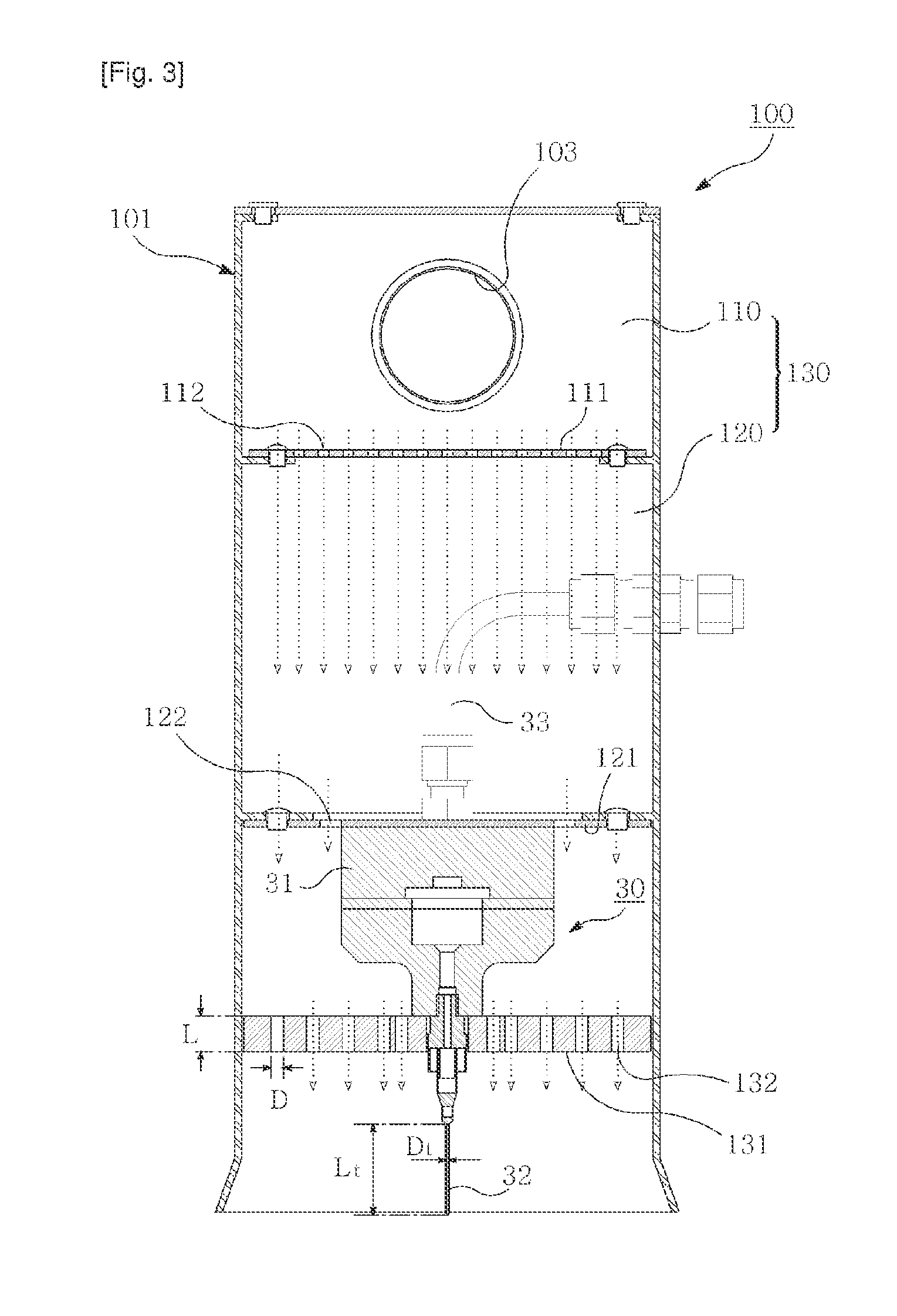
The present invention describes a method of producing nanofibers by using laminar flows of process gas to adjust the temperature and humidity of a spinning zone. This results in fibers with uniform and small diameters. The use of laminar flows also ensures uniform volatilization of a solvent, leading to increased productivity. By maintaining the temperature of a supplied solution constant, the viscosity of the solution is also kept uniform, resulting in fibers with uniform diameters. The method also reduces air conditioning costs by controlling only the temperature and humidity of the spinning zone, as compared to a typical method where the entire spinning room is operated. Additionally, a secondary distribution plate is positioned a certain distance from the end of a spinning nozzle to prevent spun fibers from scattering backward and adhering to the plate.

Problems solved by technology

When the humidity of a spinning zone is increased in order to decrease the diameter of nanofibers, the volatilization speed of a solvent is decreased, which may cause a film defect that jeopardizes the cleanliness of a product.
In this case, although a typical electro-blowing spinning apparatus is appropriate to massively produce nanofibers, since injected air is within in a turbulence flow region and a transition range, an air turbulence may occur in a spinning zone to thereby destabilize the solidification speed of nanofibers.
However, such air conditioner systems increase equipment and energy costs.

Method used


Image

  • Electrospinning apparatus for producing nanofibres and capable of adjusting the temperature and humidity of a spinning zone
  • Electrospinning apparatus for producing nanofibres and capable of adjusting the temperature and humidity of a spinning zone
  • Electrospinning apparatus for producing nanofibres and capable of adjusting the temperature and humidity of a spinning zone

Examples


Embodiment Construction

[0032]Hereinafter, preferred embodiments of the present invention will now be described in detail with reference to the accompanying drawings.

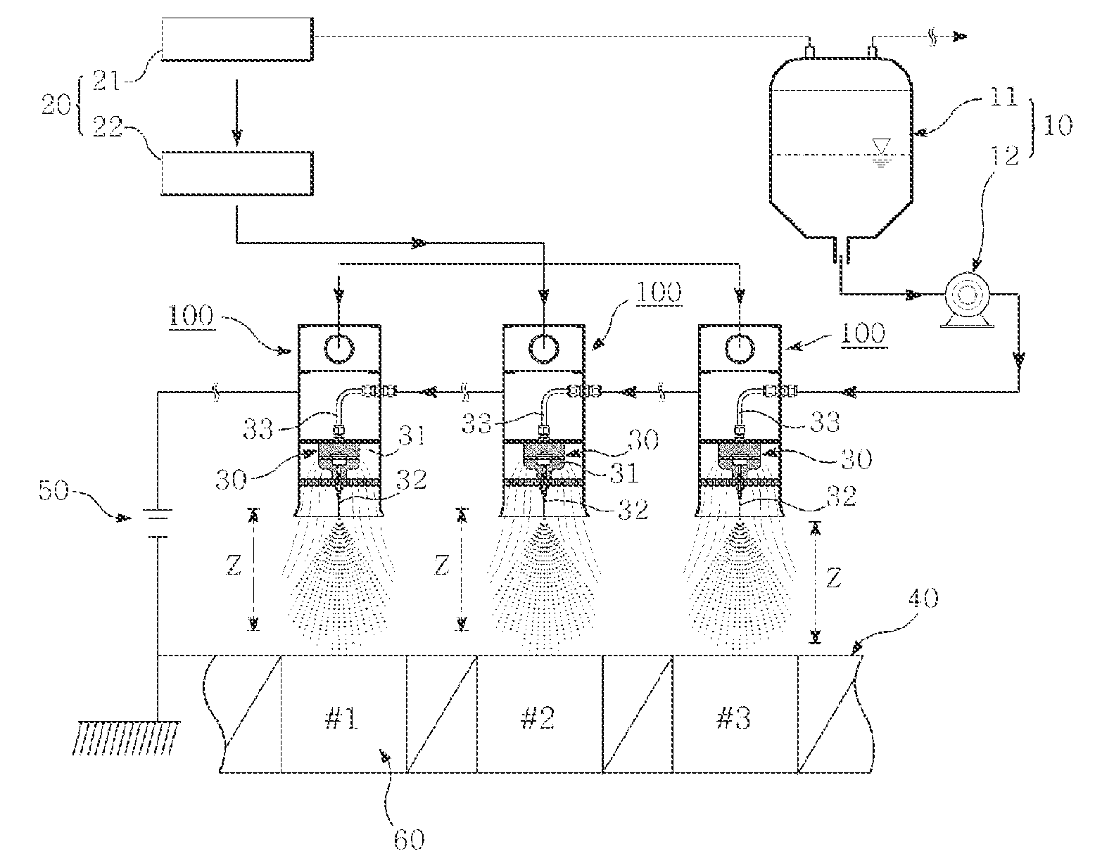
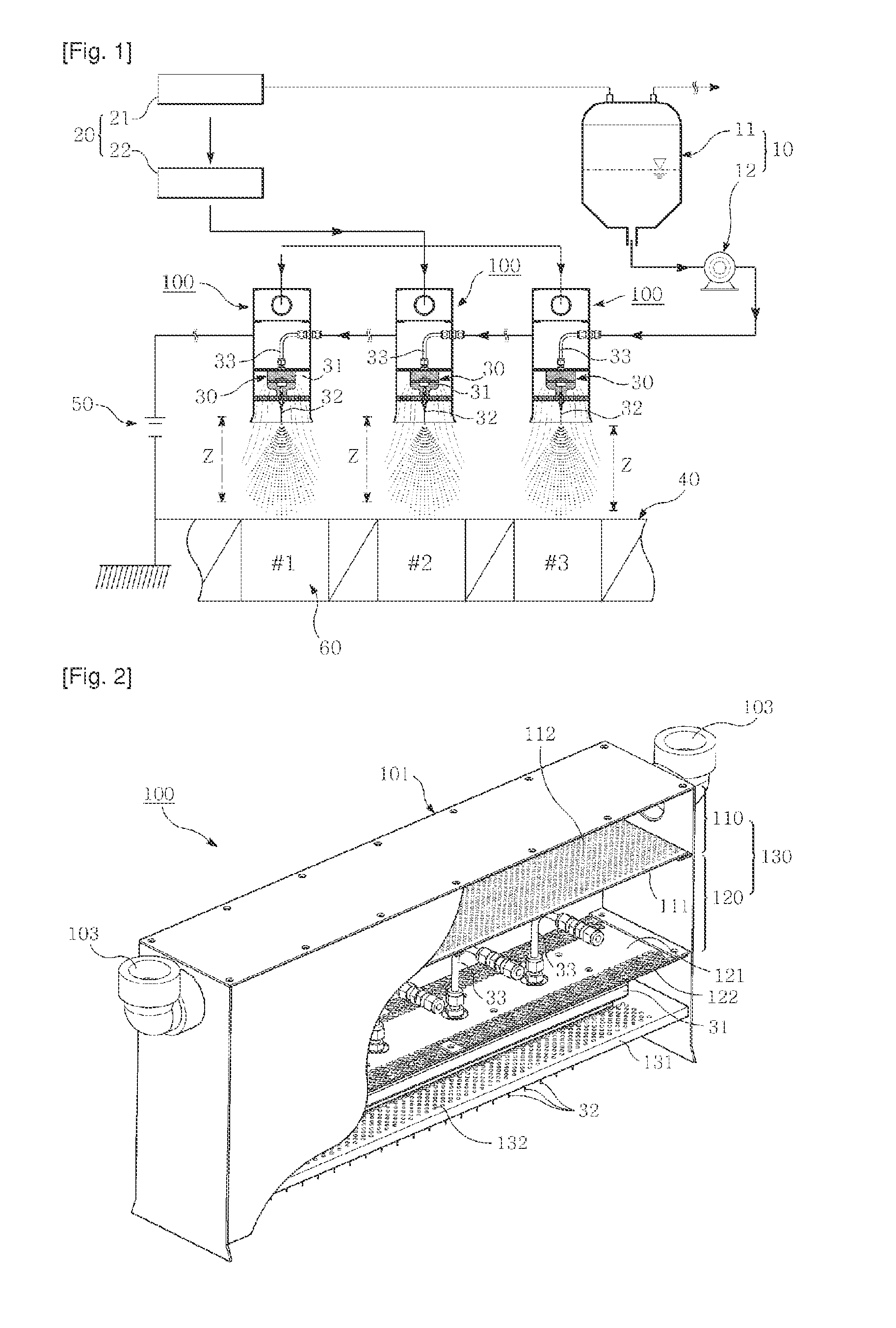
[0033]Referring to FIG. 1, an electrospinning apparatus for producing nanofibers according to an embodiment of the present invention includes: a spinning solution supply unit 10 which includes a spinning solution storage tank 11 for storing a spinning solution formed by dissolving a nanofiber source in a solvent, and a quantitative supply pump 12 for quantitatively supplying the spinning solution from the spinning solution storage tank 11; a plurality of spinning units 30, each of which uses the spinning solution supplied from the quantitative supply pump 12 to spin nanofibers through spinning nozzles 32 installed on a nozzle block 31; a nanofiber-collecting unit 40 which collects the nanofibers spun through the spinning nozzles 32; a power supply 50 which applies voltage across the spinning unit 30 and the nanofiber-collecting unit 40 to form...


PUM

PropertyMeasurementUnit
distanceaaaaaaaaaa
temperatureaaaaaaaaaa

Abstract

Provided is an electrospinning apparatus for producing nanofibers, including: a spinning solution supply unit (10); a spinning unit (30) that includes spinning nozzles (32) and a nozzle block (31) in which the spinning nozzles (32) are equidistantly arranged and supported; a nanofiber-collecting unit (40) which collects nanofibers spun from the spinning unit (30); a power supply (50) which forms an electric field in a spinning zone (Z); a process gas supply unit (20) which generates and supplies process gas to control the temperature and humidity of the spinning zone (Z) to a range appropriate for electrospinning conditions for nanofibers; and a process gas laminar flow distribution device (100) which fractionates the process gas supplied from the process gas supply unit (20), into laminar flows within the process gas laminar flow distribution device (100), and distributes the process gas from an upper portion of the spinning unit (30) to the spinning zone (Z).

Description

TECHNICAL FIELD[0001]The present invention relates to an electrospinning apparatus for producing nanofibers, and more particularly, to an electrospinning apparatus for providing laminar flows of process gas to a spinning zone to adjust the temperature and humidity of the spinning zone to a range appropriate for nanofiber electrospinning conditions.BACKGROUND ART[0002]In general, an electrospinning apparatus for producing nanofibers includes: a spinning solution (polymer solution) storage tank; a spinning solution quantitative transfer device; a nozzle block; a plurality of nozzles provided to the nozzle block; a collector for collecting nanofibers spun through the nozzles; and a power supply for applying voltage across the nozzle block and the collector.[0003]When nanofibers are produced using such a typical electrospinning apparatus, the types of used polymer and solvent, the concentration of a polymer solution, and the temperature and humidity of a spinning room may affect the dia...

Claims


Application Information

Patent Timeline
Patent Type & Authority Applications(United States)
IPC IPC(8): D01D5/06
CPCD01D5/0061D01D5/0069
Inventor KIM, HA CHUL
Owner FIBRANE
Learn More