Current collector for flexible electrode, method of manufacturing same, and negative electrode including same

a technology of current collector and flexible electrode, which is applied in the direction of cell components, final product manufacturing, sustainable manufacturing/processing, etc., can solve the problems of reducing battery capacity, deteriorating battery output characteristics, and greatly deteriorating battery performance, so as to prevent the delamination of negative active material, excellent capacity retention, and excellent capacity characteristics

Inactive Publication Date: 2013-01-10
UNIST ULSAN NAT INST OF SCI & TECH
View PDF1 Cites 51 Cited by
  • Summary
  • Abstract
  • Description
  • Claims
  • Application Information

AI Technical Summary

Benefits of technology

[0031]The technology of the present invention provides a current collector for a flexible electrode, and a rechargeable lithium battery having excellent capacity retention by preventing the delamination of a negative active material even when an electrode is bent, while having excellent capacity characteristics.

Problems solved by technology

Since the decrease in the adherence between the negative active material and the copper current collector and an active material delamination phenomenon occurring from the decreased adherence increase the internal resistance of the battery, the performance of the battery is greatly deteriorated, such as deteriorated output characteristics of the battery and decreased battery capacity.
As a result, the charge-discharge cycle characteristics of the battery are deteriorated and the cycle-life of the battery is reduced.

Method used


Image

  • Current collector for flexible electrode, method of manufacturing same, and negative electrode including same
  • Current collector for flexible electrode, method of manufacturing same, and negative electrode including same
  • Current collector for flexible electrode, method of manufacturing same, and negative electrode including same

Examples


example 1

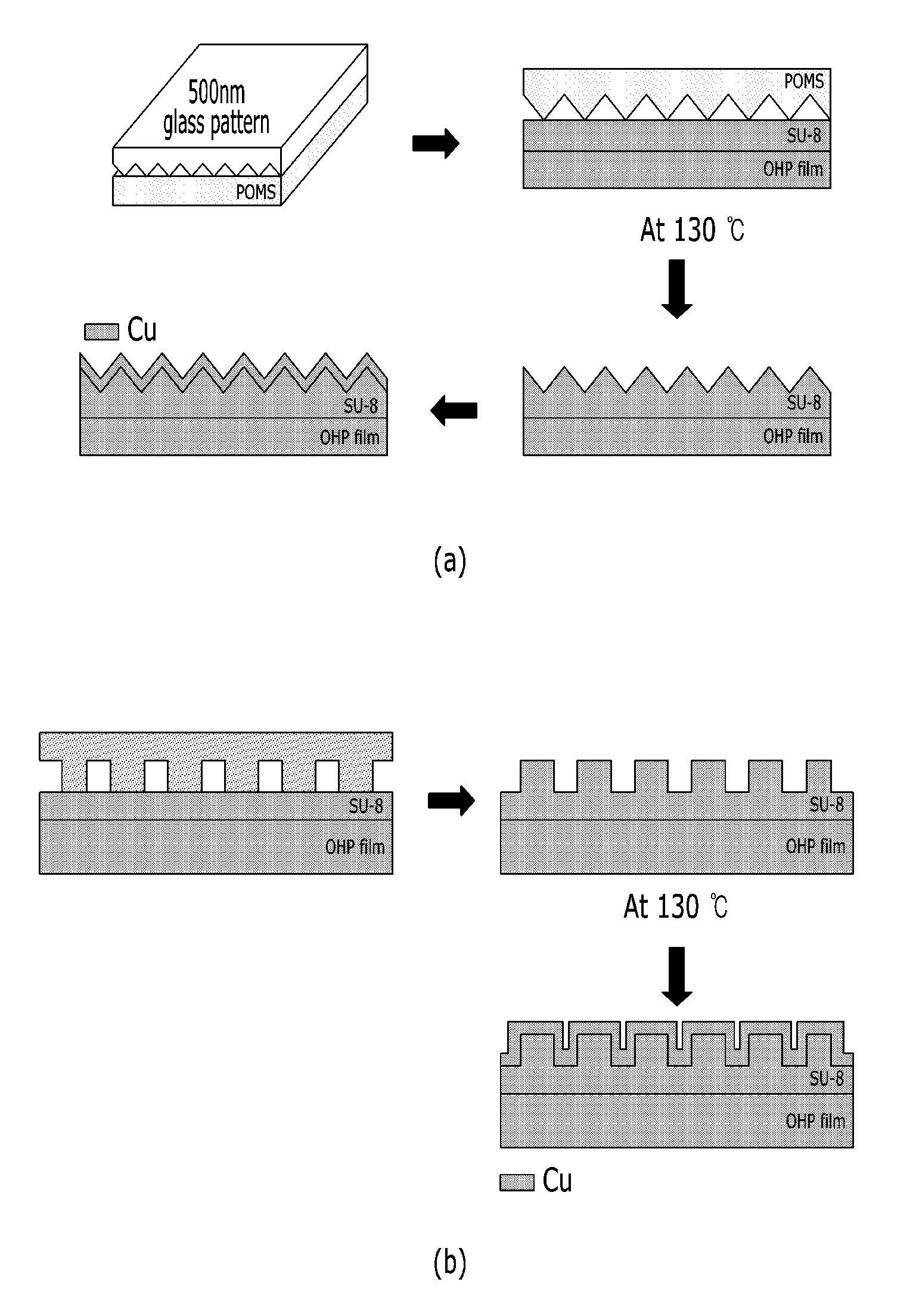
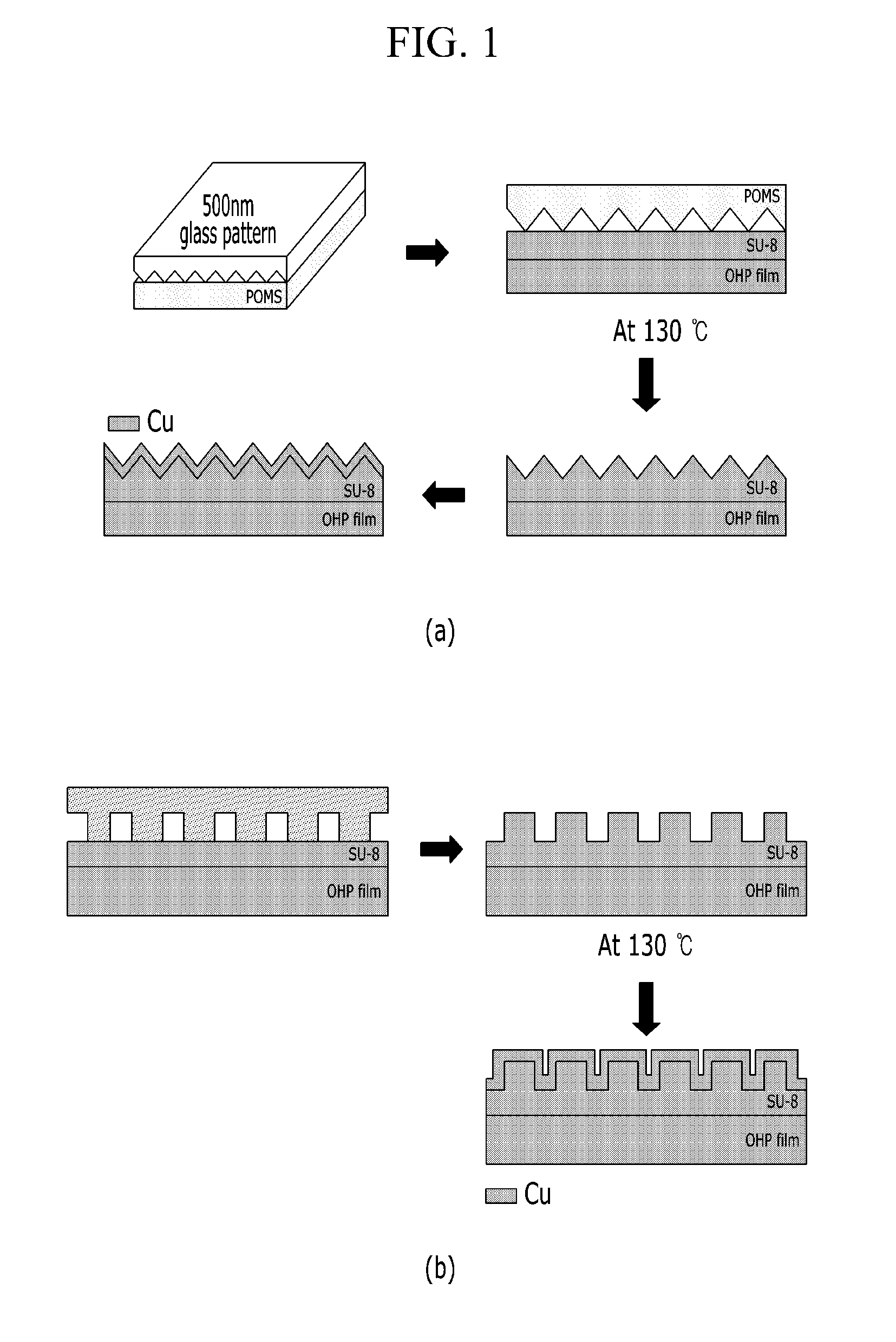
[0082]FIG. 1 is flowchart describing a method for manufacturing a current collector for a flexible electrode in accordance with one embodiment of the present invention. In FIG. 1, the difference between (a) and (b) is the shape of the surface of a polymer layer (i.e., the shape of protrusions and grooves). The manufacturing is the same except for the surface shape. Specific examples are as follows.

[0083]Polyethylene terephthalate was used as a polymer substrate. The polymer substrate was precipitated in tetrahydrofuran for 1 hour and then cleaned with distilled water.

[0084]The cleaned polyethylene terephthalate polymer substrate was spin-coated with SU-8 (MicroChem, Su-8 2000.5), which is a cross-linkable epoxy-based polymer, at 3000 rpm for about 1 minute.

[0085]After the coating process, the polymer substrate was dried in an oven at 80° C. for 1 hour to improve the adhesion between the polyethylene terephthalate polymer substrate and the spin-coated polymer layer.

[0086]The polymer ...

experimental example

[0091]Atomic Force Microscope (AFM) Photograph

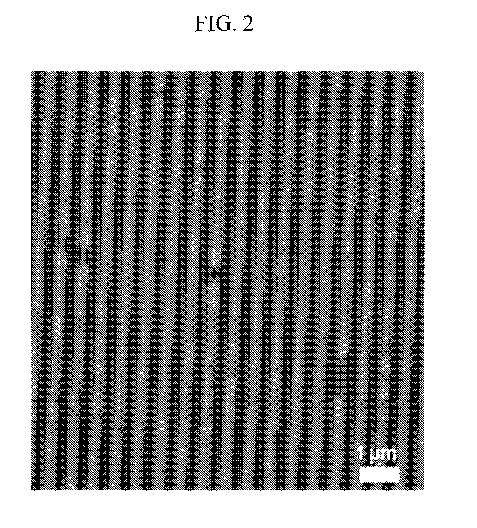
[0092]FIG. 2 is an atomic force microscopic photograph after protrusions and grooves are formed on a polymer layer.

[0093]FIG. 3 is an atomic force microscopic photograph after the polymer layer with the protrusions and grooves goes through ultraviolet radiation and heat treatment.

[0094]FIG. 4 is an atomic force microscopic photograph after the polymer layer is deposited with copper.

[0095]It may be seen from FIGS. 2, 3, and 4 that the shape of protrusions and grooves was not changed even though the protrusions and grooves were formed on the polymer layer and then went through the ultraviolet ray radiation process, the heat treatment process, and the process of depositing copper on the polymer layer.

[0096]Surface Photograph

[0097]FIG. 5 is a surface photograph of the polymer layer of Example 1 including protrusions and grooves.

[0098]Although FIG. 5 is a photograph of a plastic pattern where protrusions and grooves were formed which was take...


PUM

PropertyMeasurementUnit
heightaaaaaaaaaa
heightaaaaaaaaaa
Raaaaaaaaaaa

Abstract

Disclosed are a current collector for a flexible electrode, a method of manufacturing the same, and a negative electrode including the same. The current collector for a flexible electrode includes: a flexible polymer substrate; a cross-linkable polymer layer disposed on the polymer substrate; and a metal layer disposed on the cross-linkable polymer layer, wherein the surface of the cross-linkable polymer layer includes a plurality of protrusions and grooves.

Description

CROSS-REFERENCE TO RELATED APPLICATION[0001]This application claims priority to and the benefit of Korean Patent Application No. 10-2010-0027557 filed in the Korean Intellectual Property Office on Mar. 26, 2010, the entire contents of which are incorporated herein by reference.BACKGROUND OF THE INVENTION[0002](a) Field of the Invention[0003]A current collector for a flexible electrode, a method of manufacturing the same, and a negative electrode including the same are disclosed.[0004](b) Description of the Related Art[0005]As portable devices, such as mobile phones, laptop computers, personal digital assistants (PDA), electronic papers, and so forth, are down-sized and become increasingly thinner recently, researchers are paying more attention to down-sizing rechargeable lithium batteries and portability of the rechargeable lithium batteries, which are energy sources of the portable devices.[0006]The rechargeable lithium batteries include: a lithium transition element composite oxid...

Claims


Application Information

Patent Timeline
Patent Type & Authority Applications(United States)
IPC IPC(8): H01M4/66C25D5/54H01M4/04
CPCB32B7/045B32B15/085B32B15/09B32B15/095B32B2457/00Y02E60/122H01M4/661H01M4/667H01M4/668H01M4/70H01M4/13B32B7/05Y02E60/10Y02P70/50
Inventor PARK, SOOJINCHO, JAE-PHILSONG, HYUN-KONLEE, JUNG-IN
Owner UNIST ULSAN NAT INST OF SCI & TECH
Why Eureka
Try Eureka