Anode active material for lithium secondary battery and method of preparing the same

a lithium secondary battery and active material technology, applied in the field of anode active material for lithium secondary batteries, can solve the problems of low capacity per unit mass of graphite, difficulty in preparing high-capacity lithium secondary batteries using graphite, volume expansion and contraction, etc., and achieve excellent capacity characteristics of secondary batteries. , the effect of improving initial efficiency and life characteristics

Active Publication Date: 2019-07-16
LG ENERGY SOLUTION LTD
View PDF42 Cites 3 Cited by
  • Summary
  • Abstract
  • Description
  • Claims
  • Application Information

AI Technical Summary

Benefits of technology

[0014]Since an anode active material according to an embodiment of the present invention includes a silicon-based composite including Si and SiO2 in a grain state and the SiO2 is crystalline SiO2, the reaction between amorphous SiO2 and lithium in an electrolyte may be excluded. Thus, since the crystalline SiO2 is included in the silicon-based composite, excellent capacity characteristics of a secondary battery may be maintained and initial efficiency and life characteristics may be improved when the silicon-based composite is used as an anode active material.

Problems solved by technology

However, graphite has a low capacity per unit mass of 372 mAh / g and a high-capacity lithium secondary battery may be difficult to be prepared by using graphite.
However, since a metal, such as silicon (Si), tin (Sn), and aluminum (Al), is alloyed with lithium during charge and discharge, volume expansion and contraction may occur.
Thus, cycle characteristics of the battery may degrade.
However, since a reaction between lithium (Li) and oxygen (O) forming by-products is represented by an irreversible reaction, initial efficiency may be decreased.
However, it has limitations in that charge and discharge cycle characteristics may not be sufficiently improved and an x value in SiO, may be difficult to be controlled by a conventional synthesis method.

Method used


Image

  • Anode active material for lithium secondary battery and method of preparing the same
  • Anode active material for lithium secondary battery and method of preparing the same
  • Anode active material for lithium secondary battery and method of preparing the same

Examples


example 1

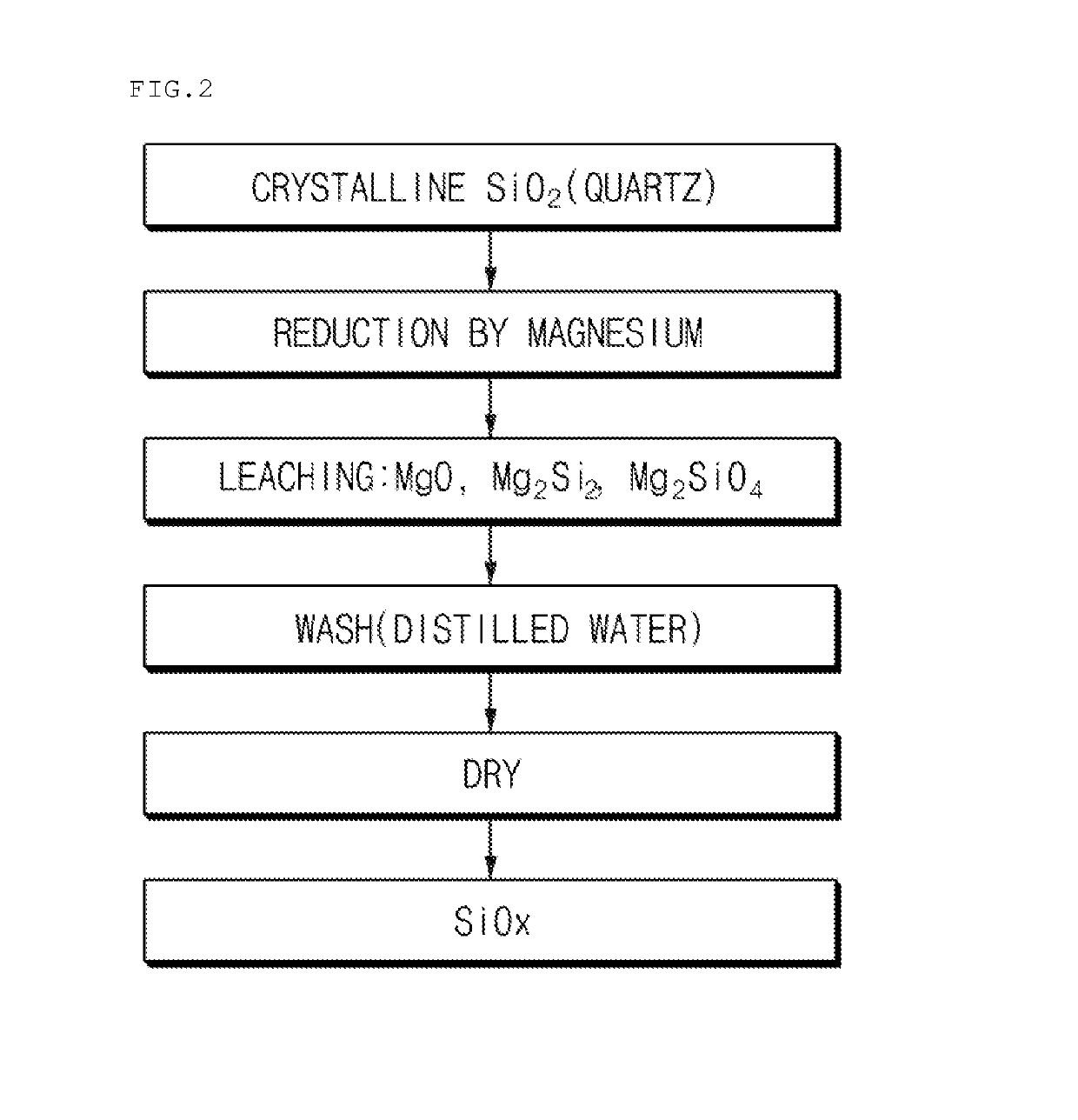
[0063]100 g of crystalline SiO2 powder and 41 g of Mg powder as a metal reducing agent were mixed and then put in a reaction vessel of a thermal reduction chamber. Subsequently, the temperature of the chamber was increased to 570° C. Thereafter, Ar was used as an inert gas, and Ar was supplied at a flow rate of about 800 sccm. Also, the reaction was performed using a rotary kiln as the reaction vessel. The thermal reduction reaction was performed for 8 hours, and after 8 hours, the chamber temperature was decreased to room temperature. A product in the reaction vessel was collected to prepare a silicon-based composite. Reduced MgO or the like was removed from the prepared silicon-based composite using HCl (1N). In this case, scanning electron microscope (hereinafter, referred to as “SEM”) images of the prepared silicon-based composite are presented in FIG. 4.

example 2

[0066]The silicon-based composite prepared in Example 1 as an anode active material, acetylene black as a conductive agent, and polyvinylidene fluoride as a binder were mixed at a weight ratio of 95:1:4 and the mixture was mixed with a N-methyl-2-pyrrolidone solvent to prepare a slurry. One surface of a copper current collector was coated with the prepared slurry to a thickness of 30 μm, dried and rolled. Then, an anode was prepared by punching into a predetermined size.

[0067]10 wt % fluoroethylene carbonate based on a total weight of an electrolyte solution was added to a mixed solvent, which includes 1.0 M LiPF6 and an organic solvent prepared by mixing ethylene carbonate and diethyl carbonate at a weight ratio of 30:70, to prepare an non-aqueous electrolyte solution.

[0068]A lithium foil was used as a counter electrode, a polyolefin separator was disposed between both electrodes, and a coin-type half cell was then prepared by injecting the electrolyte solution.

experimental example 1

surement

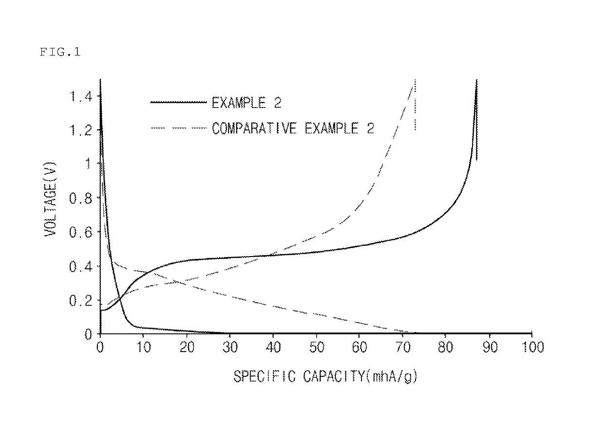
[0070]In order to investigate initial discharge capacities of the coin-type half cells prepared in Example 2 and Comparative Example 2, the coin-type half cells were charged at 0.1 C to a voltage of 4.2 V under constant current / constant voltage (CC / CV) conditions and charged to a current of 0.005 C under a constant current (CC) condition at 25° C. in the first cycle. After the coin-type half cells were left standing for 30 minutes, initial discharge capacities were measured by discharging the cells at 0.1 C to a voltage of 3 V.

[0071]Also, in order to investigate initial efficiencies of the coin-type half cells prepared in Example 2 and Comparative Example 2, the coin-type half cells prepared in Example 2 and Comparative Example 2 were charged at 0.1 C to a voltage of 5 mV and charged to a current of 0.005 C at 5 mV under constant current / constant voltage (CC / CV) conditions at 23° C., and then discharged at 0.1 C to a voltage of 1.5 V under a constant current (CC) condition t...


PUM

PropertyMeasurementUnit
diameteraaaaaaaaaa
particle diameteraaaaaaaaaa
temperatureaaaaaaaaaa

Abstract

Provided are an anode active material for a lithium secondary battery including a silicon-based composite formed of silicon (Si) and crystalline SiO2, wherein the Si and crystalline SiO2 are in the form of grains, a method of preparing the same, and a lithium secondary battery including the anode active material.Since an anode active material according to an embodiment of the present invention includes a silicon-based composite including Si and SiO2 in a grain state and the SiO2 is crystalline SiO2, the reaction between amorphous SiO2 and lithium in an electrolyte may be excluded. Thus, since the crystalline SiO2 is included in the silicon-based composite, excellent capacity characteristics of a secondary battery may be maintained and initial efficiency and life characteristics may be improved when the silicon-based composite is used as an anode active material.

Description

CROSS-REFERENCE TO RELATED APPLICATIONS[0001]The present application is a national phase entry under 35 U.S.C. § 371 of International Application No. PCT / KR2014 / 010352 filed Oct. 31, 2014, which claims priority from Korean Application No. 10-2013-0131827 filed Oct. 31, 2013 and Korean Application No. 10-2014-0149928 filed Oct. 31, 2014, all of which are hereby incorporated herein by reference.TECHNICAL FIELD[0002]The present invention relates to an anode active material for a lithium secondary battery, a method of preparing the same, and a lithium secondary battery including the anode active material.BACKGROUND ART[0003]Lithium secondary batteries, which have been in the spotlight as a power source of portable and small electronic devices, may exhibit high discharge voltages that are two times or more than those of batteries using a typical alkaline aqueous solution by using an organic electrolyte solution. Thus, the lithium secondary batteries exhibit high energy density.[0004]Oxid...

Claims


Application Information

Patent Timeline
Patent Type & Authority Patents(United States)
IPC IPC(8): H01M4/48H01M10/0525C01B33/023H01M10/052H01M4/38H01M4/36H01M4/13
CPCH01M4/48C01B33/023H01M4/13H01M4/364H01M4/483H01M10/0525H01M4/386H01M2220/30H01M10/052H01M4/134Y02E60/10C01B33/02C01B33/113H01M4/1395H01M4/38
Inventor KIM, HYUN CHULLEE, YONG JUKIM, EUN KYUNG
Owner LG ENERGY SOLUTION LTD
Why Eureka
Try Eureka