Gas sensor, analyzer and method for measuring oxygen concentration of a respiratory gas

a gas sensor and analyzer technology, applied in the field of gas sensors, analyzers and methods for measuring oxygen concentration of respiratory gases, can solve the problems of affecting the response time of the sensor, being too large to fit into a mainstream sensor, and weak absorption

Inactive Publication Date: 2013-01-24
GENERAL ELECTRIC CO
View PDF4 Cites 19 Cited by
  • Summary
  • Abstract
  • Description
  • Claims
  • Application Information

AI Technical Summary

Benefits of technology

[0009]The above-mentioned shortcomings, disadvantages and problems are addressed herein which will be understood by reading and understanding the following specification.

Problems solved by technology

Oxygen can be measured using chemical sensors or fuel cells, but they are normally too bulky to fit into a mainstream sensor and, although they have a limited lifetime, they are not designed to be single use and must therefore be protected from direct contact with the patient gas to avoid contamination.
This is expensive and also influences the response time of the sensor.
However, this absorption is very weak and the signal from the short distance across the respiratory tube becomes too noisy to be useful.
Problems that have to be attended to are temperature and humidity dependence as well as drift caused by ageing.
Because the measuring chamber is in the breathing circuit, it is easily contaminated by mucus or condensed water.
It is not possible make a zeroing measurement using a reference gas during normal operation.
A really compact CO2 and O2 gas analyzer has been technically very challenging.
This kind of thermistor is fastened to the window coated with the luminophore, but unfortunately is not able to follow constantly changing temperature fast enough as is the case with the respiratory measurement.
Also the main stream adapter with the thermistor fastened to the window is too expensive to be disposable and should therefore be sterilized after each use.

Method used


Image

  • Gas sensor, analyzer and method for measuring oxygen concentration of a respiratory gas
  • Gas sensor, analyzer and method for measuring oxygen concentration of a respiratory gas
  • Gas sensor, analyzer and method for measuring oxygen concentration of a respiratory gas

Examples


Embodiment Construction

[0020]Specific embodiments are explained in the following detailed description making a reference to accompanying drawings. These detailed embodiments can naturally be modified and should not limit the scope of the invention as set forth in the claims.

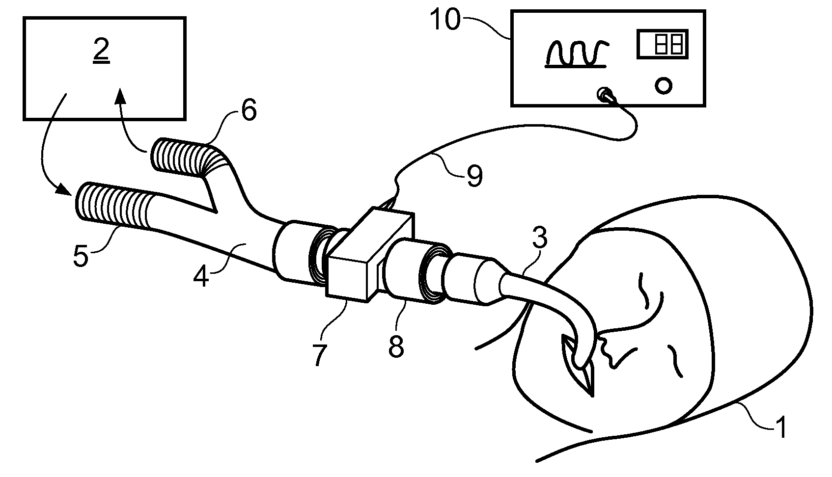
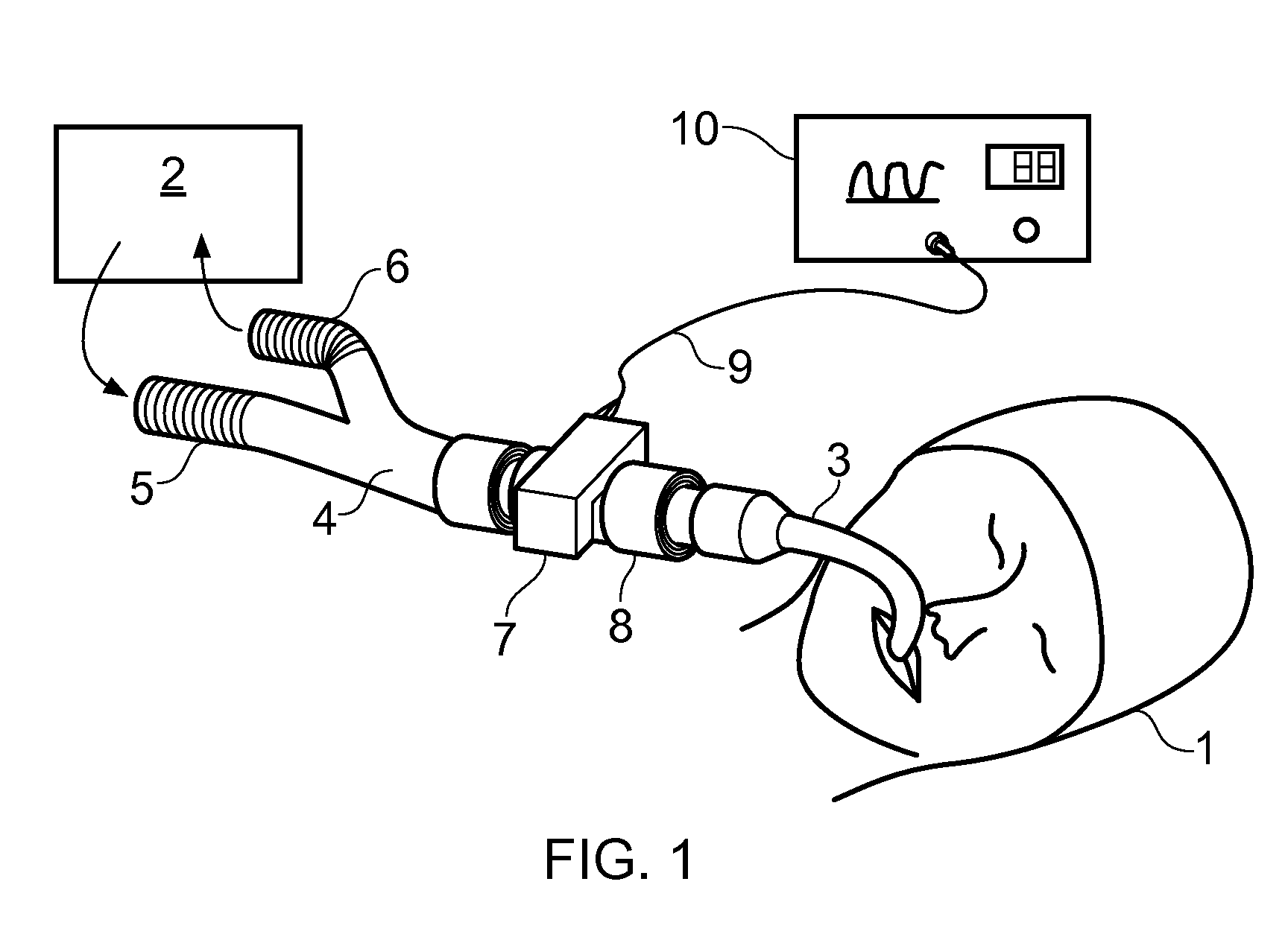
[0021]A gas analyzer 7 for measuring a respiratory gas such as oxygen is shown in FIG. 1. This technology may be applied in clinical multigas analyzers of mainstream type. The gas analyzer 7 such as a medical mainstream gas analyzer may be measuring directly across the respiratory tube of an intubated patient 1 as shown in FIG. 1. The patient 1 is connected to a ventilator 2 using an intubation tube 3, a Y-piece 4, an inspiratory limb 5 and an expiratory limb 6. The airway adapter 8 is connected to the intubation tube. The gas analyzer 7 which comprises components of the airway adapter is electrically connected via cable 9 to the patient monitor 10. The gases measured may be besides oxygen O2 also carbon dioxide CO2 and possibly other ...


PUM


Abstract

A gas sensor is disclosed herein. The gas sensor includes an emitter for emitting radiation to a body at least partly coated with a luminophore emitting luminescent radiation indicative of an oxygen concentration when in contact with a respiratory gas. The gas sensor also includes a filter for transmitting the luminescent radiation emitted by the luminophore and an oxygen detector for receiving the luminescent radiation transmitted by the filter. The gas sensor also includes an infrared thermometry unit for receiving a thermal radiation from the luminophore. A gas analyzer and a method for measuring oxygen concentration of a respiratory gas are also provided.

Description

BACKGROUND OF THE INVENTION[0001]This disclosure relates generally to a gas sensor including an emitter for emitting radiation to a body at least partly coated with a luminophore emitting luminescent radiation indicative of an oxygen concentration when in contact with a respiratory gas, a filter for transmitting the luminescent radiation emitted by the luminophore and an oxygen detector for receiving the luminescent radiation. This disclosure also relates to a gas analyzer and method for measuring oxygen concentration of a respiratory gas[0002]In anesthesia or in intensive care, the status of a patient is often monitored by analyzing the gas inhaled and exhaled by the patient for its content. For this reason either a small portion of the respiratory gas is diverted to a gas analyzer or the gas analyzer is directly connected to the respiratory circuit. The former analyzer is of sidestream type, the latter is named mainstream because of its ability to measure directly across the respi...

Claims


Application Information

Patent Timeline
Patent Type & Authority Applications(United States)
IPC IPC(8): A61B5/08
CPCG01N21/643G01N21/8422G01J5/0003G01J5/046G01J5/0853G01J5/0862G01J1/58G01J3/42G01J5/28G01J5/0014G01J5/0802
Inventor KARLSSON, KAI
Owner GENERAL ELECTRIC CO
Why Eureka
Try Eureka