Signal processing in guided wave cutoff spectroscopy

a technology of signal processing and guided wave, applied in the direction of optical radiation measurement, instruments, spectrometry/spectrophotometry/monochromators, etc., can solve problems such as attenuating phase noise, and achieve the effect of improving resolution and increasing measurement bandwidth

Active Publication Date: 2013-01-24
THERMO FISHER SCIENTIFIC INC
View PDF5 Cites 5 Cited by
  • Summary
  • Abstract
  • Description
  • Claims
  • Application Information

AI Technical Summary

Benefits of technology

[0041]The present system digitizes the entire final IF waveform, thereby eliminating need to wait for a previous signal to decay. Digital data prior to the desired valid signal is ignored. As valid data arrives the data is accumulated without any of the data being discarded. At some point during the valid data accumulation event the system may begin to step to the next frequency and thus will immediately begin to generate an invalid analog signal. However, there is some finite delay in the actual arrival of that invalid data at the ADC output. The present system takes advantage of this delay by continuing to accumulate valid data until the arrival time of the valid data. Once acquired, the data from all ADC inputs can be processed to the detection bandwidth limit and the total energy or net power associated with the waveform can be computed. Once normalized to the reference channel data, the total energy computation becomes a received signal frequency point in the total response spectrum of the post MUT measurement cell output signal.
[0042]The present system employs coherent signal generation and conversions, allowing the acquired signal to be phase compared to a similarly acquired phase reference signal in order to determine the phase shift in the post MUT signal exiting the measurement cell. Phase shift change with frequency change is a function of velocity, while velocity is a function of dielectric constant. Although the controlling dielectric constant occurs at the single cutoff frequency, in some cases additional information about the MUT can be derived from the dielectric constant at different frequencies. Thus, the change in phase at various frequencies can provide dielectric constant related information at these frequencies. The quality of any velocity measuring system is a function of measurement bandwidth. The present guided wave system operates over large measurement bandwidths and is able to quantify the effects of changes in dielectric constant at different frequencies with improved resolution that is attributable to the increased measurement bandwidth. The coherent heterodyne architecture of the present invention can measure amplitude and phase change by examining the same received signal.

Problems solved by technology

Further, the RF and LO signals are phase synchronous, thereby attenuating phase noise.

Method used


Image

  • Signal processing in guided wave cutoff spectroscopy
  • Signal processing in guided wave cutoff spectroscopy
  • Signal processing in guided wave cutoff spectroscopy

Examples


Embodiment Construction

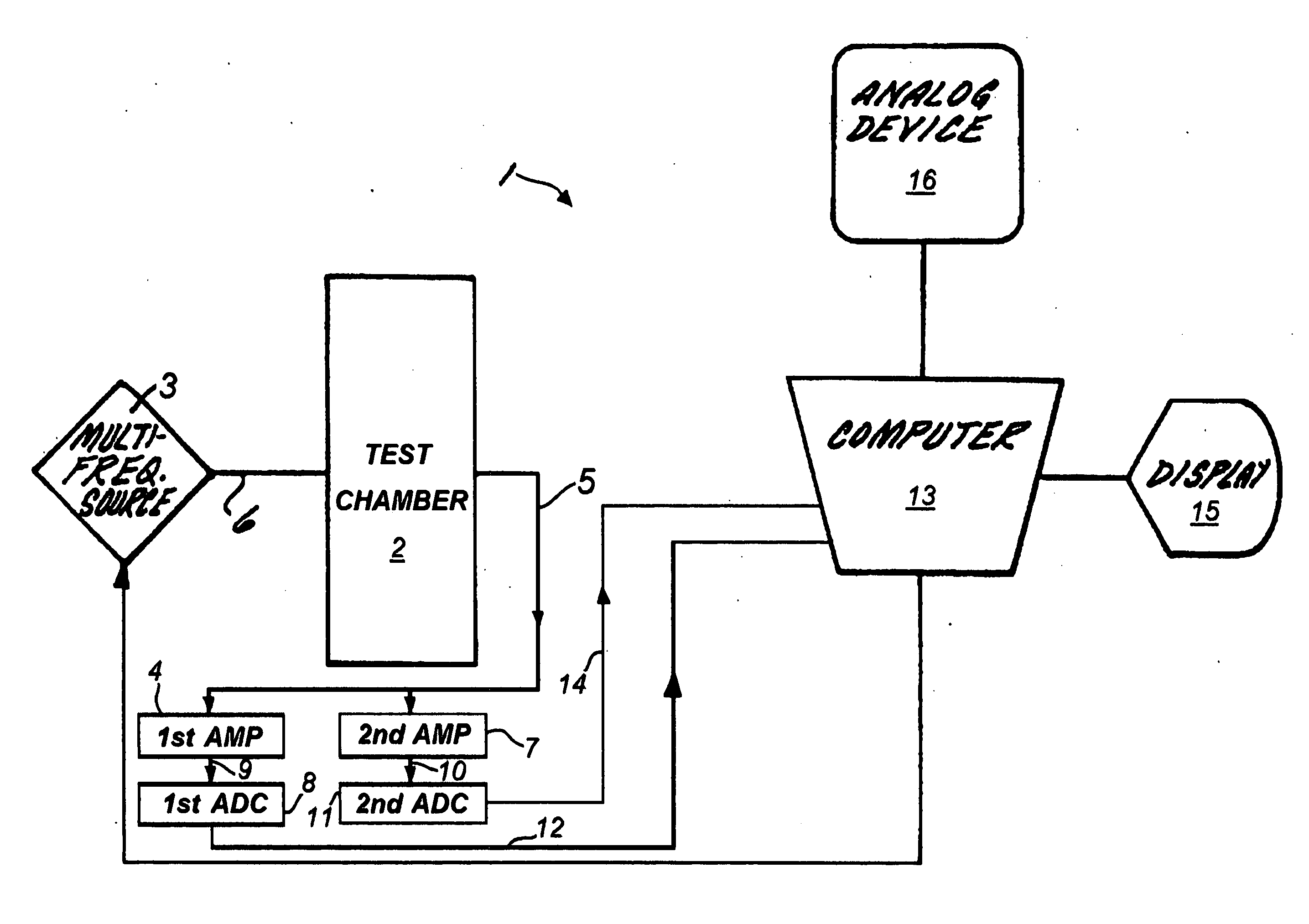
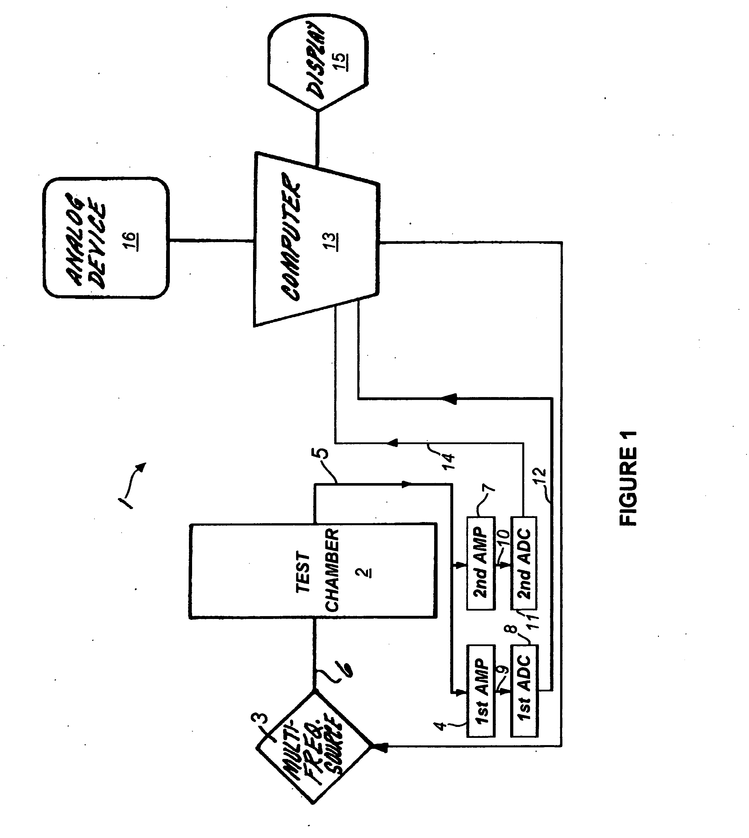
[0058]The present invention is shown generally at 1 in the block diagram of FIG. 1, where the test chamber 2 includes some means for introducing a material to be tested, the means typically being a pipe that transports the material under test through the chamber as a flowable material such as a liquid or slurry. A swept or stepped frequency source 3 is interconnected via path 6 with the chamber 2, the source 3 typically being an oscillator capable of generating multiple radio frequencies in the range of thirty megahertz (30 MHz) to four gigahertz (GHz). Depending upon the material under test and the physical characteristics of the chamber 2, some portion of the radio frequency spectrum is emitted into the chamber and passes through the material under test that is residing at that moment within the chamber. The test chamber 2 is shaped and dimensioned to create frequency dependent responses when subjected to electromagnetic radiation, typically ranging from RF and into the microwave ...


PUM


Abstract

The present invention includes a guided microwave spectroscopy system (1) that eliminates the need for an automatic gain control feature by providing multiple signal processing paths having differing fixed voltage gains. An emitted signal which exits a test chamber (2) containing a material under test is simultaneously amplified by at least a first fixed gain amplifier (4) and a second fixed gain amplifier (7). The output signal of each amplifier is separately digitized and then normalized for further digital signal processing by a computer (13) in order to determine parameters of the material under test which may have variable microwave radiation characteristics that are a function of the frequency of the signal emitted into the test chamber. During the signal processing step a system clock (121) causes the computer to sample only an integral number of complete output signal cycles. A calibration protocol (136-154) is conducted based on laboratory samples of each potential material to be processed by the system (1).

Description

FIELD OF THE INVENTION[0001]This invention relates generally to the field of Guided Microwave Spectroscopy, and more particularly to the observation and analysis of multiple signal sources when analyzing the dielectric properties of a material under test.DESCRIPTION OF RELATED TECHNOLOGY[0002]The use of a microwave waveguide cutoff frequency to characterize properties of materials is commonly referred to as Guided Microwave Spectroscopy (GMS) and is described, for example, in U.S. Pat. Nos. 5,331,284 and 5,455,516. GMS systems measure the dielectric properties of the material being tested, referred to as the MUT (Material under Test). The measurement technique places, often as a flowing slurry, the MUT in a measurement cell. This cell includes an electromagnetic waveguide which is frequently called a microwave waveguides However, the microwave region is broadly considered to relate to frequencies above 1 Gigahertz (GHz). Typical GMS systems can operate from well below to well above ...

Claims


Application Information

Patent Timeline
Patent Type & Authority Applications(United States)
IPC IPC(8): G06F19/00G01R23/16G16Z99/00
CPCG01R23/16G06F19/00G01N23/02G06F2219/00G01J3/00G01R27/2623G01N22/04G06F17/40G16Z99/00
Inventor ERB, TOM LEE
Owner THERMO FISHER SCIENTIFIC INC
Why Eureka
Try Eureka