Mixed gas supply apparatus

a gas supply device and gas supply technology, applied in the direction of instruments, process and machine control, transportation and packaging, etc., to achieve the effect of shortening the gas displacement time, improving semiconductor productivity and gas utilization efficiency, and quick gas displacement of the manifold portion

a gas supply device and gas supply technology, applied in the direction of instruments, process and machine control, transportation and packaging, etc., to achieve the effect of shortening the gas displacement time, improving semiconductor productivity and gas utilization efficiency, and quick gas displacement of the manifold portion

US20130025718A1Active Publication Date: 2013-01-31FUJIKIN INC

Image

  • Mixed gas supply apparatus
  • Mixed gas supply apparatus
  • Mixed gas supply apparatus

Examples


first embodiment

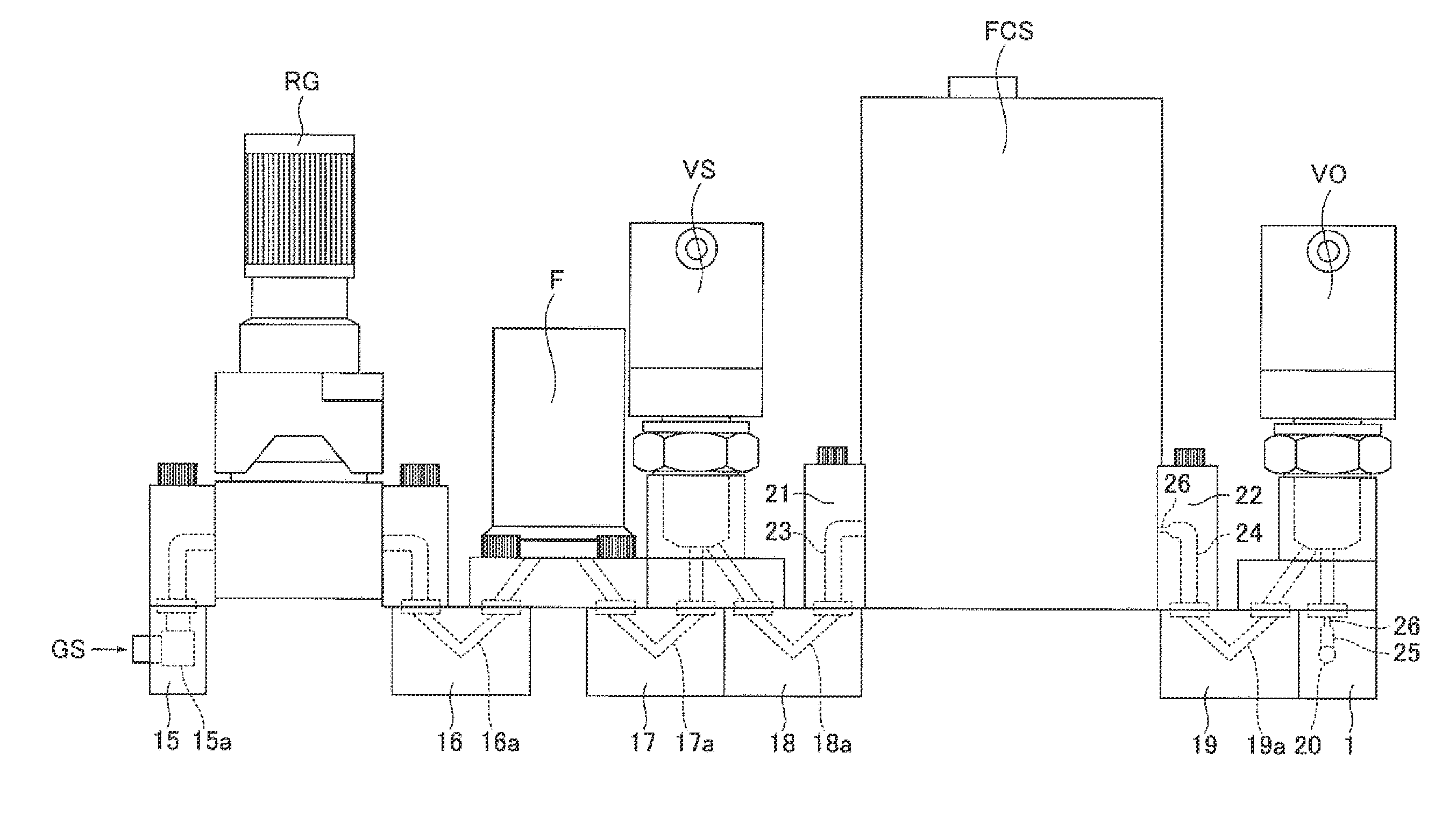
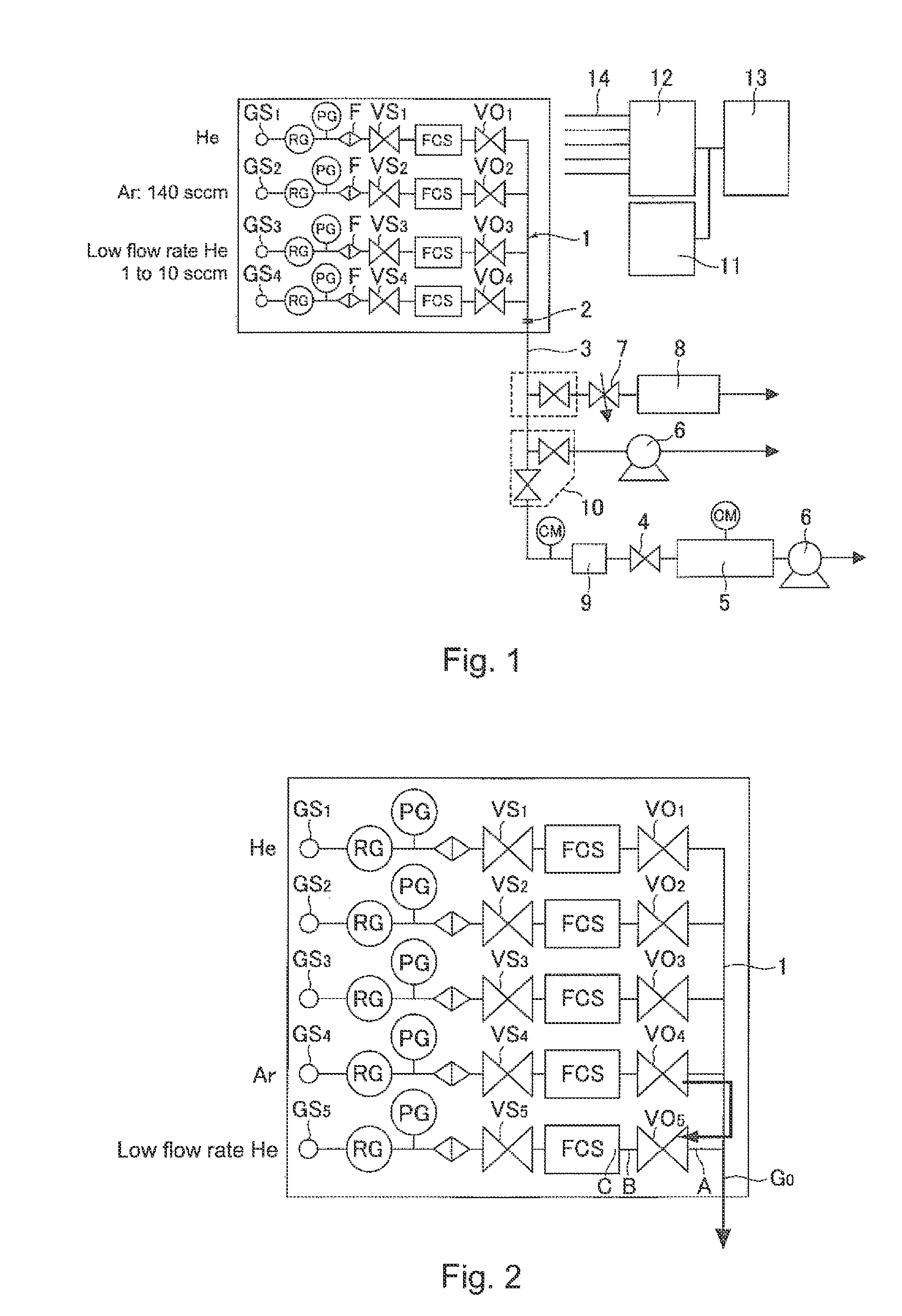
[0073]FIG. 10 is a system diagram of a mixed gas supply device according to the present invention, and FIG. 11 is a front schematic diagram thereof. In FIGS. 10 and 11, the reference symbols GS1 to GSn denote gas supply ports, the reference symbol RG denotes a pressure regulator, the reference symbol F denotes a filter, the reference symbols VS1 to VSn denote inlet side valves, the reference symbol FCS denotes a pressure type flow rate control device, the reference symbols VO1 to VOn denote outlet side switching valves, and the reference symbol 1 denotes a manifold. In addition, in the present embodiment, the pressure type flow rate control device is used as a flow rate control device. However, as a matter of course, a thermal type flow rate control device MFC may be used in place of the pressure type flow rate control device.

[0074]Furthermore, the reference symbols 15 to 19 denote mounting tables wherein corresponding symbols 15a to 19a denote flow passages formed in the respective...

second embodiment

[0085]That is, the gasket type orifice 30 is inserted to be attached in a gap located between the outlet side end of the gas outlet side passage 27 of the outlet side switching valve VO and the inlet side end of the gas passage 25 of the manifold 1, and the gasket type orifice 30 is hermetically interposed by sandwiching the main body of the outlet side switching valve VO and the manifold 1 to press fix those components together. In addition, in FIG. 15, the gasket type orifice 30 is used. However, as a matter of course, an orifice itself may be in any form.

[0086]FIG. 16 is a graph showing relationships between a flow rate (sccm) of a low flow rate He gas and back-diffusion of Ar gas into the He gas using sizes of the orifice 30 as parameters. It is understood from FIG. 16 that, in the case where the flow rate of the low flow rate helium gas is approximately 3 sccm or more, back-diffusion into the low flow rate helium gas is prevented by making the caliber of the orifice 30 into 0.6...


PUM

PropertyMeasurementUnit
inner diameteraaaaaaaaaa
outer diameteraaaaaaaaaa

Abstract

A mixed gas supply device includes a plurality of gas supply lines arranged in parallel that include flow rate control devices and outlet side switching valves, wherein gas outlets of respective outlet side switching valves communicate with a manifold, and another gas supply line at a position close to a mixed gas outlet of the manifold supplies a low flow rate gas, wherein an outlet side of the flow rate control device and an inlet side of the outlet side switching valve are hermetically connected via an outlet side connecting fitting of the flow rate control device and a mounting table having a gas passage, wherein a small hole portion is provided at a part of a flow passage at the outlet side connecting fitting and / or a flow passage, which makes the outlet side switching valve and a mixed gas flow passage in the manifold communicate with one another.

Description

[0001]This is a National Phase Application in the United States of International Patent Application No. PCT / JP2010 / 006261 filed Oct. 22, 2010, which claims priority on Japanese Patent Application No. 2010-035762, filed Feb. 22, 2010. The entire disclosures of the above patent applications are hereby incorporated by reference.TECHNICAL FIELD OF THE INVENTION[0002]The present invention relates to improvement of a mixed gas supply device for a semiconductor manufacturing apparatus. Specifically, the present invention relates to a mixed gas supply device that is configured to be capable of rapidly switching among a plurality of gases to supply those without causing backflow or back-diffusion thereof, which makes it possible to shorten a process time, decrease a gas loss, and downsize a mixed gas manufacturing apparatus.BACKGROUND OF THE INVENTION (BACKGROUND ART)[0003]In recent years, in the field of a semiconductor manufacturing apparatus, downsizing of the apparatus, lowering of manuf...

Claims


Application Information

Patent Timeline
31 Jan 2013
Publication
US20130025718A1
IPC
F17D1/00
CPC
B01J4/02; H01L21/67017; G05D11/132; Y10T137/87249
Inventors
NAGASE, MASAAKI; DOHI, RYOUSUKE