Modified hot runner systems for injection blow molding

a technology of hot runner and injection molding, which is applied in the direction of synthetic resin layered products, transportation and packaging, and other domestic articles, can solve the problems of increasing the exposure of microorganisms, difficult if not impossible difficult to stretch the blow mold, etc., to achieve enhanced resistance to thermal deformation, improve the overall performance characteristics, and improve the effect of wall thickness

Active Publication Date: 2013-01-31
KEIRYO PACKAGING
View PDF2 Cites 12 Cited by
  • Summary
  • Abstract
  • Description
  • Claims
  • Application Information

AI Technical Summary

Benefits of technology

[0032]The present invention describes a method for producing preforms and containers made out of crystallizable polymers, in particular of the type used for stretch blow molded containers, and more particularly preforms and containers with optimized wall thickness, yet superior overall performance characteristics, including enhanced resistance to thermal deformation both in the body and especially the neck finish, gas permeability resistance and mechanical strength.

Problems solved by technology

Highly crystalline preforms generally are difficult, if not impossible to stretch blow mold.
It also challenges the plastic material converting industry to increase the output of its plastic material converting platforms, on processes like injection and stretch blow molding.
A particular problem associated with these hot-fill containers concerns the thermal stability of both the body, but especially the neck finish of the container throughout the hot filling process, because increase in temperature during the process induces molecular relaxation and shrinkage in the container material.
Any container part made entirely of amorphous or only slightly semi-crystalline PET may not have enough dimensional stability during a standard hot-fill process to resist the relaxation process and hence meet the specifications required when using standard threaded closures.
Unacceptable volume shrinkage of the container and / or especially of the neck area may create leaks between the neck and closure, thus increasing exposure to micro-organisms, whilst increasing gas ingress and / or egress.
This can lead to non-specification compliant quality issues and, in case of food applications, to potentially consumer hazardous situations when pathological micro-organisms are able to grow inside the packed food matrix.
These repeated cycles of thermal exposure make it difficult to maintain the overall shape, appearance and threaded neck finish within the tolerances required to ensure adequate functionality and / or general consumer acceptance.
However, the required capital investments, the increased manufacturing processing time and costs for specific materials and / or auxiliaries lead to an increased overall cost of ownership and increased total product cost.
As previously stated, the overall cost of producing a container is very important and needs to be tightly controlled because of competitive market and business pressures.
Again, this requires an additional heating step and increased processing time.
Generally, this involves more complex preform injection molding procedures to achieve the necessary layered structure in the finish.
All these methods significantly increase the cost of ownership.
Exceeding these limits and entering ranges of too high stretch ratios lead to the creation of micro voids and premature container failure.
A particular problem when blow molding remains generating enhanced mechanical strength in the neck finish and in the bottom portion of the container in light of the negligible respectively low stretch ratios in these specific areas.
Especially in the case of containers intended for filling with carbonated soft drinks this local reduction in strength leads to more severe container deformation and consequently to a reduction of dissolved carbon dioxide in the soft drink and to a decreased shelf life.
A particular limitation, state of the art production methods suffer from, stems from the preheating prior to stretch blow molding the container and more specifically to the heat history heat-set containers are subjected to.
This thermal treatment destroys most of the stretch induced orientation as relaxation processes have ample time to develop.
As a consequence the resulting heat-set container looses a substantial amount of mechanical strength.

Method used


Image

  • Modified hot runner systems for injection blow molding
  • Modified hot runner systems for injection blow molding
  • Modified hot runner systems for injection blow molding

Examples


examples

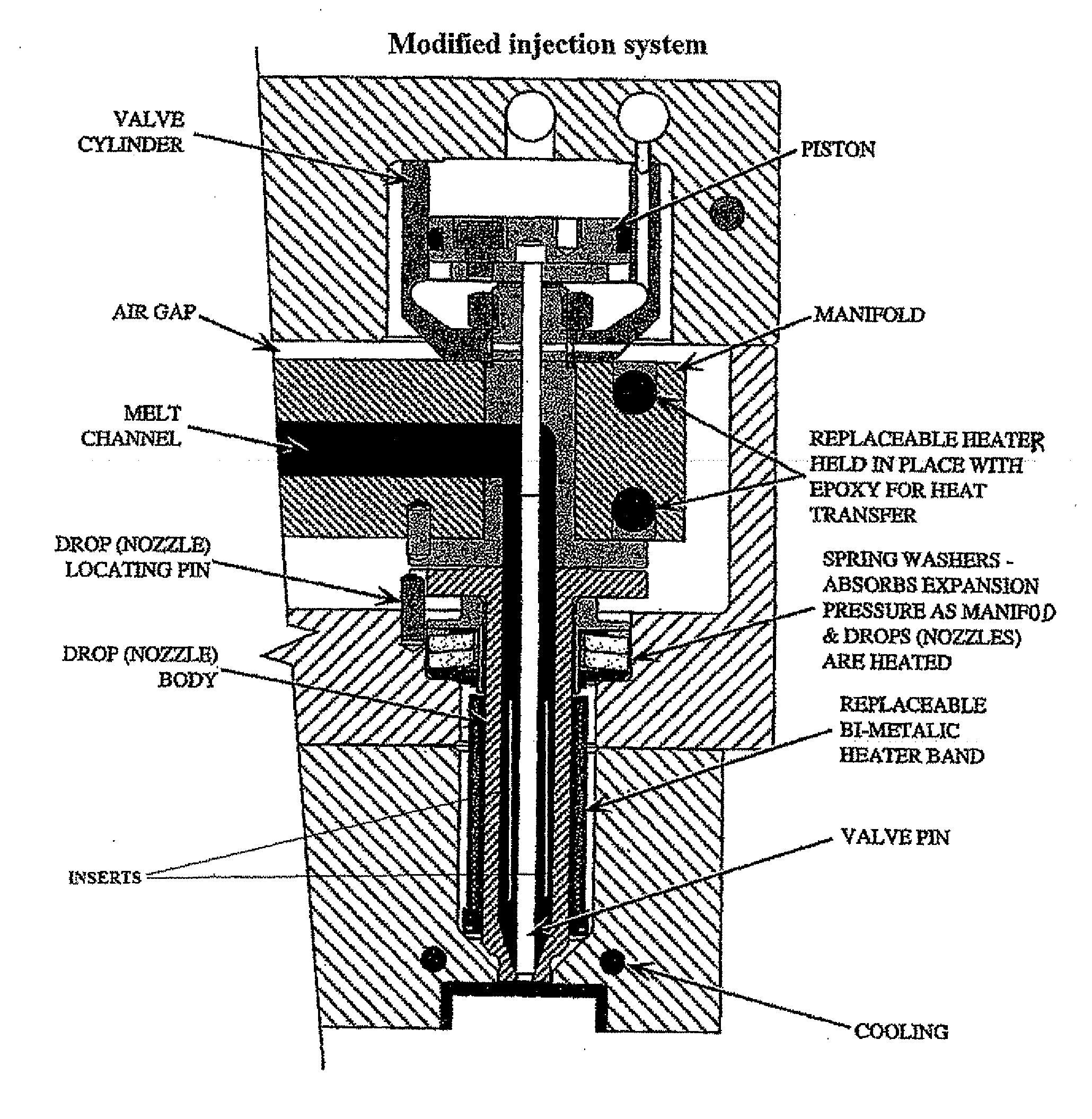
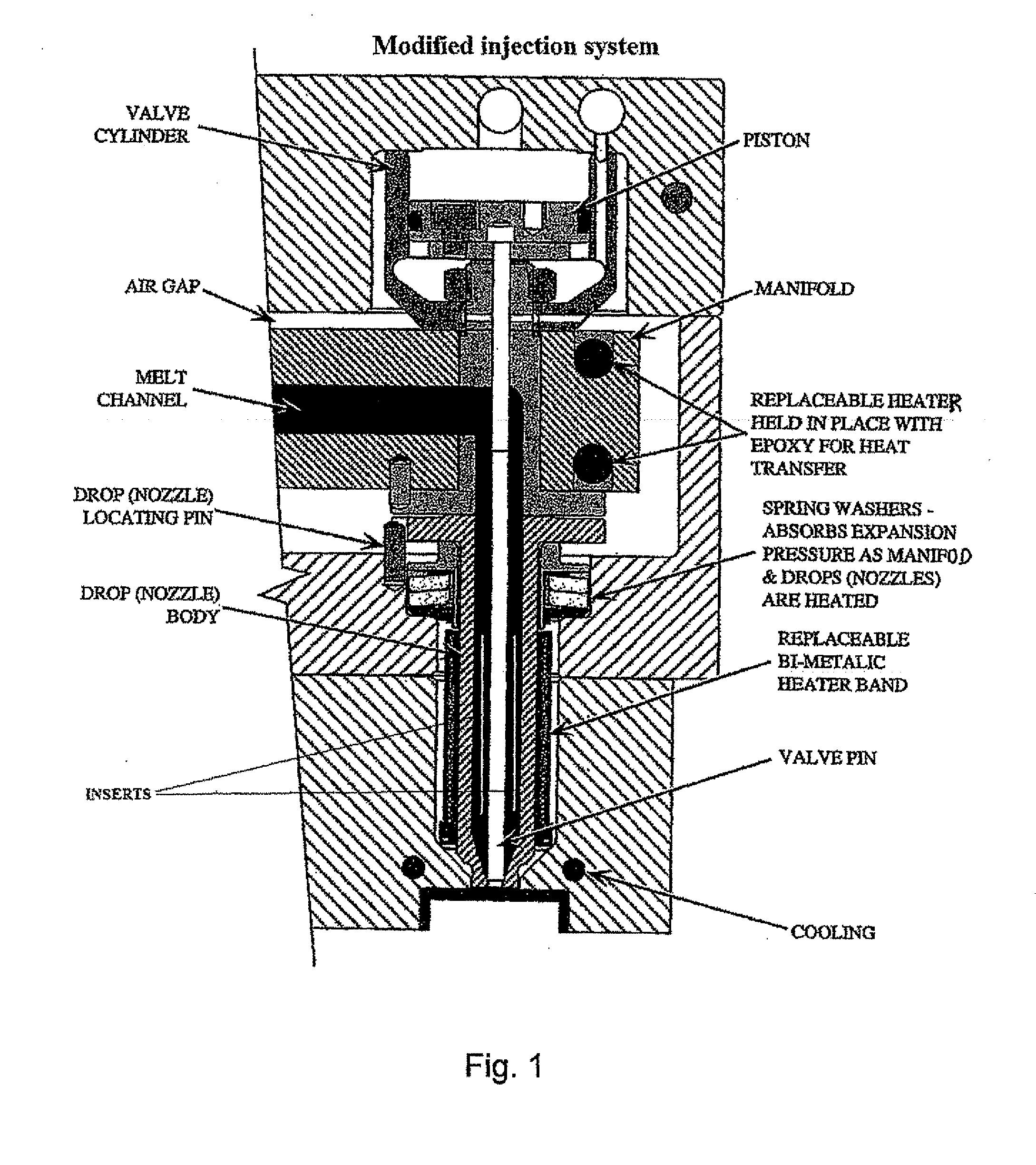
1. Injection System (FIG. 1)

[0109]a. A commercially available grade of a crystallizable polymer, being PET, is taken within a classical IV range of 0.78-0.82, like reference M&G Cobiter 80.[0110]b. The polymer material referenced under 1a. is converted on a classical injection machine, like type Huskey, operated at typical machine settings:

Extruder Barrel270-290°C.Nozzle270-290°C.Manifold275-295°C.Gates280-300°C.Mold Cooling Water10-15°C.Cycle Time10-60seconds[0111]c. Position 1b is repeated with a commercially available grade of a crystallizable polymer, being PET, with an increased IV range of 0.82-0.86, like reference M&G Cleartuf Max.[0112]d. Position 1b is repeated with a commercially available grade of a crystallizable co-polymer, being PET based, within a classical IV range of 0.78-0.82, like reference M&G Cleartuf 8006.

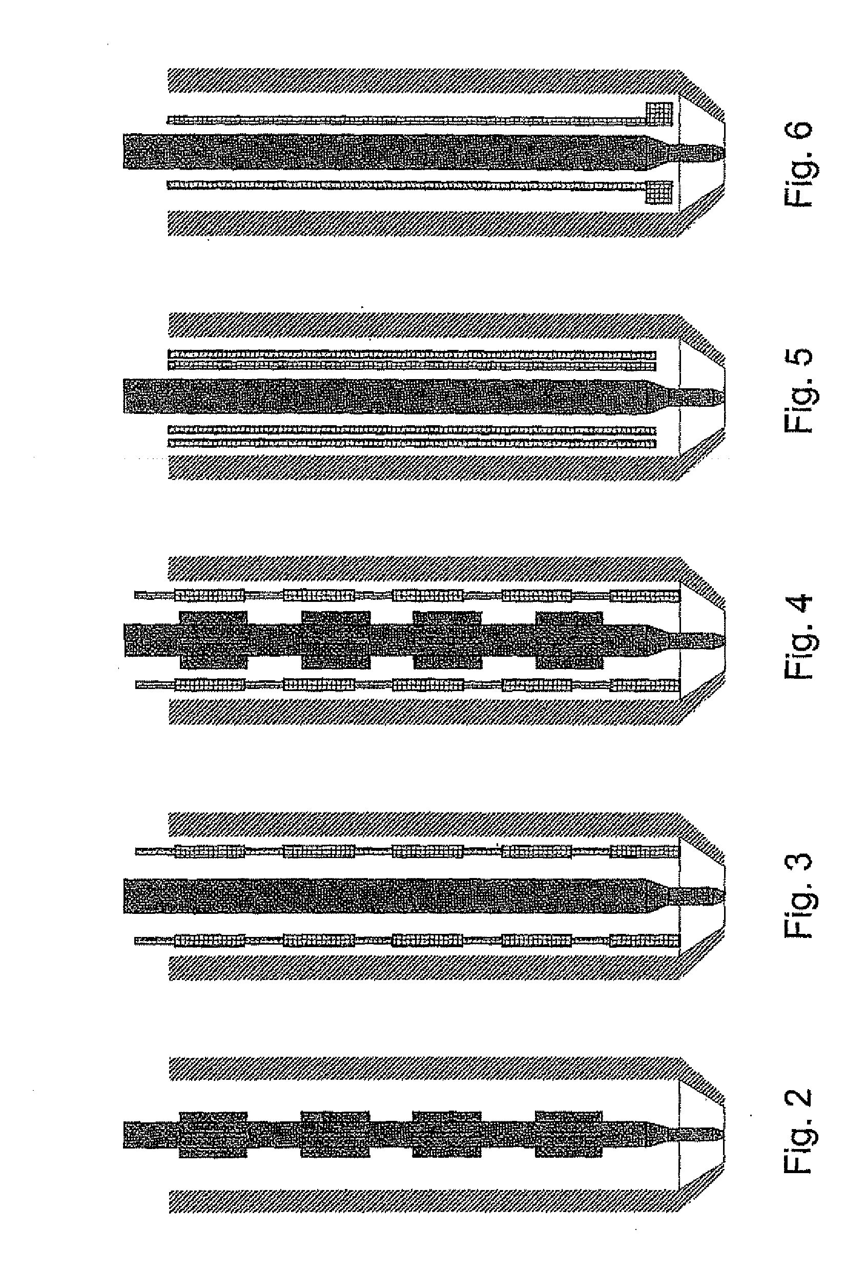
2. Hot Runner System

[0113]a. Positions 1a through 1d are executed with normal classical hot runner configuration for injected preform production.[0114]b. Posi...


PUM

PropertyMeasurementUnit
shrinkage percentageaaaaaaaaaa
thicknessaaaaaaaaaa
temperatureaaaaaaaaaa

Abstract

An injection blow molding method for making a container having the steps of injecting a molten crystallizable polymer in a preform mold via a hot runner system and biaxially stretching the preform by blowing to form a container. The method further having the step to selectively modify the flow path of the molten crystallizable polymer within the hot runner system.

Description

FIELD OF THE INVENTION[0001]The present invention relates in general to new developments of thermoplastic preforms in particular of the type used for blow molding containers, and more particularly to preforms having a crystallized neck for resistance to deformation at elevated temperatures. It also relates to a method for producing said containers and, in particular, to preforms used for their production, as well as a method for producing said preforms.BACKGROUND OF THE INVENTION[0002]The use of plastic containers as a replacement for glass or metal containers in the packaging of beverages has become increasingly popular. Several types of plastics have been used, ranging from aliphatic and aromatic polyolefins (polyethylene, polypropylene, polystyrene) over halogenated polymers (polyvinyl chloride, polyvinylidene chloride) and aliphatic polyamides (nylons) to aromatic polyesters. As far as the rigid food packaging sector is concerned, polyethylene terephthalate (PET), an aromatic po...

Claims


Application Information

Patent Timeline
Patent Type & Authority Applications(United States)
IPC IPC(8): B32B1/02C08L67/02C08G63/183B32B27/00B29C49/06
CPCB29C49/06B29C45/2806B29C45/30B29C2045/0098B29C2045/304Y10T428/1352B29C49/0005C08G63/183C08L67/03B29K2995/0041Y10T428/1397B29K2105/253B29C2049/023
Inventor DIRCX, STEVEN
Owner KEIRYO PACKAGING
Why Eureka
Try Eureka