

In vivo treatment of skin lesions by electrical nanopulses
- Summary
- Abstract
- Description
- Claims
- Application Information
AI Technical Summary
Benefits of technology
Problems solved by technology
Method used
Image

Examples
example 1
Nanopulse Generator and Electrical Nanopulses
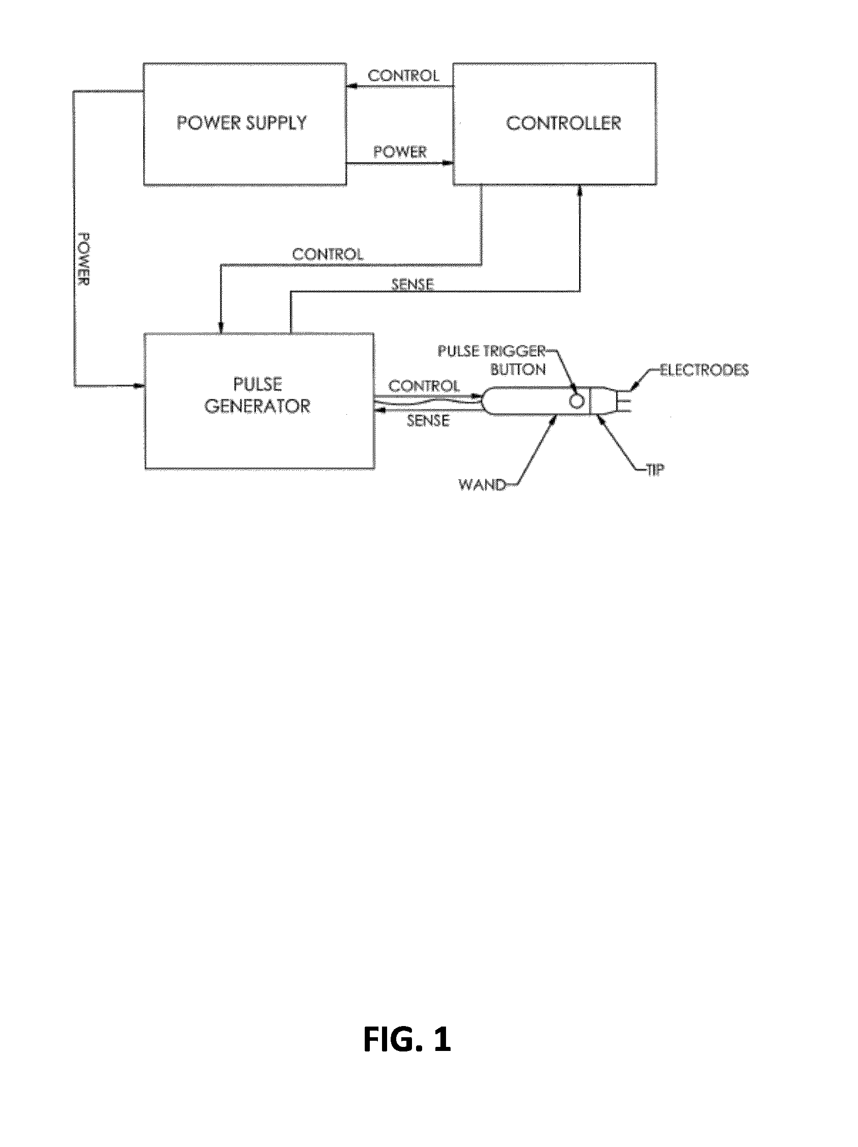
[0051]An electrical pulse generation and delivery system, schematically shown in FIG. 1, comprising a pulse generator was constructed at the Alfred E. Mann Institute for Biomedical Engineering at the University of Southern California (Los Angeles, Calif.).
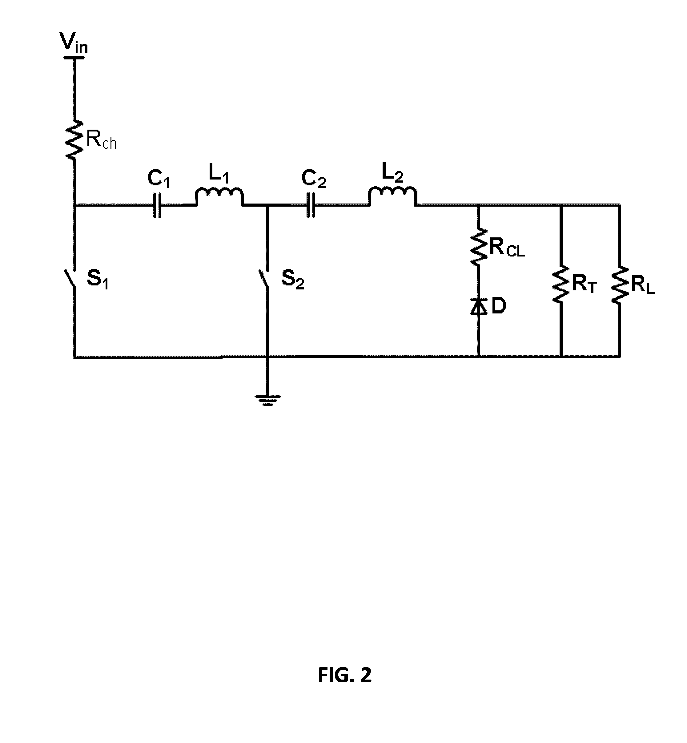
[0052]An example of the pulse generator is schematically shown in FIG. 2. This pulse generator was previously disclosed in detail in U.S. Pat. No. 7,767,433 to Kuthi et al. and in U.S. Patent Application U.S. 2010 / 0038971 to Sanders, the content of which is incorporated by reference. This pulse generator is briefly described below:
[0053]As shown in FIG. 2, the diode pulse generator may include a tank circuit consisting of inductances L1 and L2 and capacitances C1 and C2. The tank circuit may be connected in series with a diode D across which a load RL to be driven may be connected. This load may be the resistance of the lesion or tissue. The pulse generator may include a switching system...
example 2
Mouse Model and Formation of Skin Lesions
[0069]All experiments with mice were conducted after experimental procedures were approved by Institutional Animal Care and Use Committee (IACUC) of Department of Comparative Medicine Cedars Sinai Medical Center, Santa Monica, Calif. For all procedures, mice were given isofluorane anesthesia and positioned on a warming bed.
[0070]Cutaneous papillomas and squamous carcinomas were chemically induced according to an established protocol disclosed in following publications: Hennings H, Shores R, Mitchell P, Spangler E F, Yuspa S H “Induction of papillomas with a high probability of conversion to malignancy” Carcinogenesis (1985) 6:1607-10; Hennings H, Spangler E F, Shores R, Mitchell P, Devor D, Shamsuddin A K, Elgjo K M, Yuspa S H “Malignant conversion and metastasis of mouse skin tumors: a comparison of SENCAR and CD-1 mice” Environmental health perspectives (1986) 68:69-74; and Slaga T J “SENCAR mouse skin tumorigenesis model versus other strai...
examples 3 to 59
Application of Nanosecond Electrical Pulses to Skin Lesions
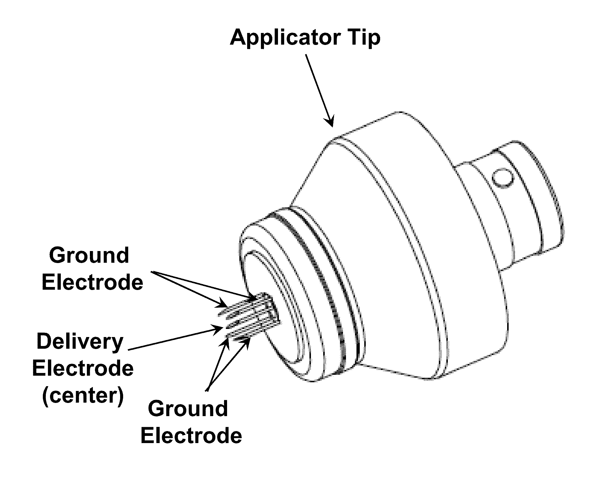
[0074]In Examples 3 to 59, the tumors, which were formed on the mice skin by following the method in the manner of Example 2, were treated by using the nanopulse generator and the applicator tip disclosed in Example 1.
[0075]To avoid formation of air pockets between the electrodes, both the tumor and the electrodes were covered with Aquasonic 100 ultrasound transmission gel (Parker Laboratories Inc., Fairfield, N.J., USA). Electrical pulses with varying duration, amplitude and number were delivered to the skin lesion to determine effects of these pulse parameters on tumor treatment.
[0076]Photographs of tumors were taken before and after each treatment and also one week after the treatment to record shape of the tumor, as shown in FIG. 5 and FIG. 6 by way of example.
[0077]Tumor size was measured before each treatment and one week after the treatment by using a vernier caliper. The highest elevation of the tumor as measured fro...
PUM
 Abstract
Description
Claims
Application Information