
Projection-type photolithography system using composite photon sieve

a composite photon and photolithography technology, applied in the field of micronano fabrication, can solve the problems of high cost, low efficiency, and difficult photolithography, and achieve the effects of reducing system volume, improving photolithography efficiency, and reducing costs

Active Publication Date: 2013-02-21
INST OF MICROELECTRONICS CHINESE ACAD OF SCI
View PDF2 Cites 10 Cited by
  • Summary
  • Abstract
  • Description
  • Claims
  • Application Information

AI Technical Summary

Benefits of technology

The present disclosure is about a new type of photolithography system that uses a composite photon sieve to perform photolithography in batches quickly, efficiently, and at a lower cost. The composite photon sieve is made up of a transparent substrate and a metal film, which is compact, lightweight, and has better aberration characteristics than conventional projection objective lenses. The system can improve efficiency and cut costs by performing photolithography in batches using a mask plate. The inner portion of the composite photon sieve utilizes a first order diffractive photon sieve design, while the outer portion utilizes a third order diffractive zone plate, which improves the SNR. Overall, the composite photon sieve has advantages of high efficiency and compactness, and can be used for various photolithography applications.

Problems solved by technology

These propose harsh requirements to the designing, processing and assembling process of a projection objective lens system having a large numerical aperture and a weight of over one ton.
However, both the zone plate maskless direct writing systems and the photon sieve maskless direct writing systems belong to the direct writing photolithography systems, making them incapable of performing photolithography in batches rapidly by using the mask plate, and thus their efficiencies are much lower than that of the projection-type photolithography systems.

Method used


Image

  • Projection-type photolithography system using composite photon sieve
  • Projection-type photolithography system using composite photon sieve
  • Projection-type photolithography system using composite photon sieve

Examples


Embodiment Construction

[0034]The present disclosure will be further explained in detail in connection with specific embodiments and with reference to the drawings, and thereby objects, technical solutions, and advantages of the present disclosure will become apparent.

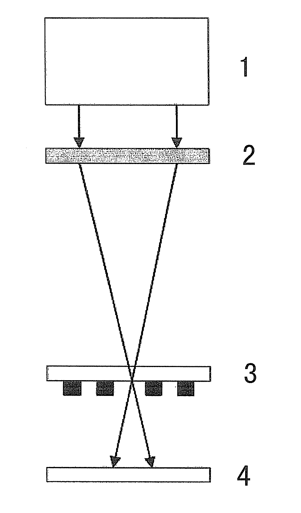
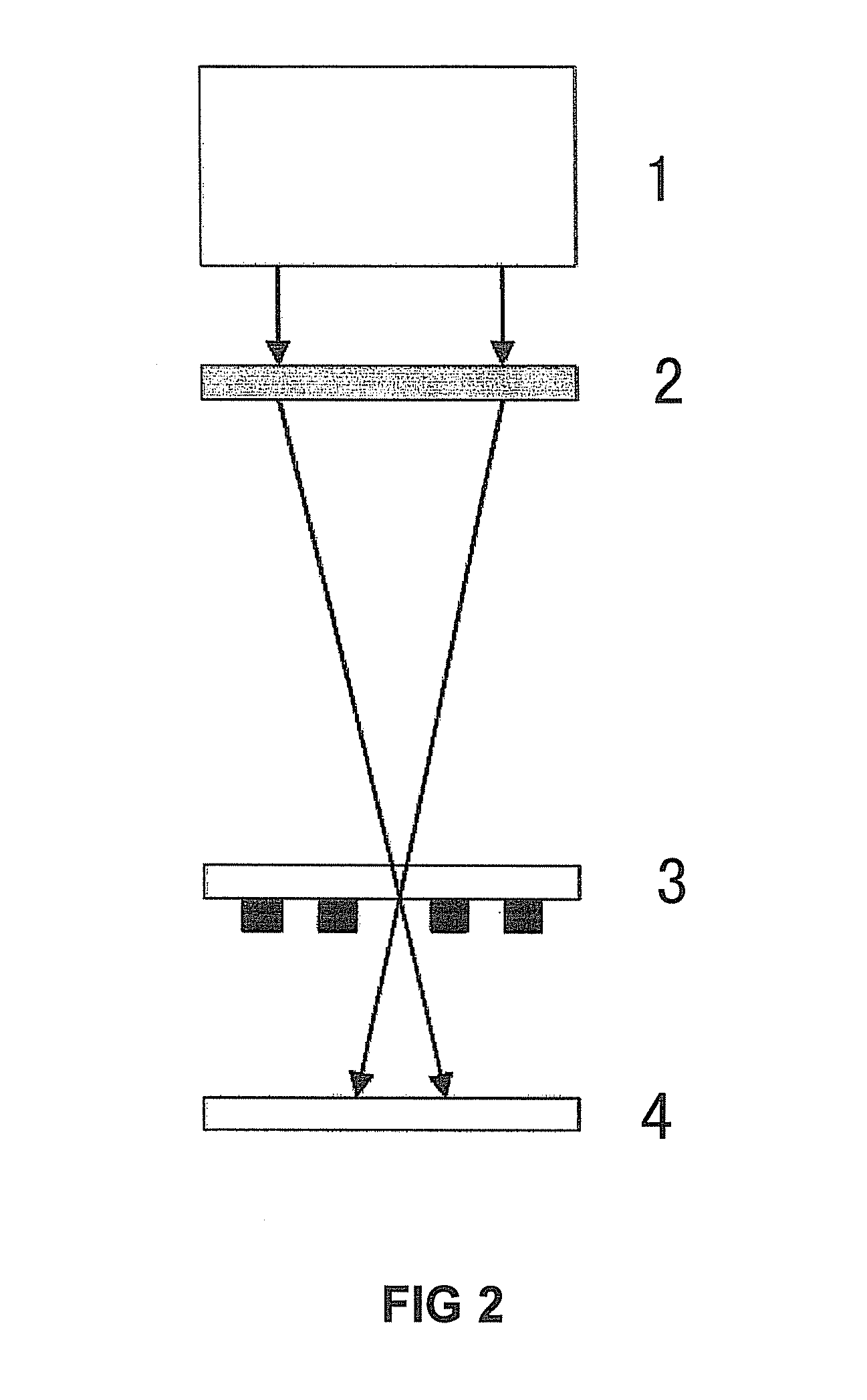
[0035]A projection-type photolithography system using a composite photon sieve according to the present disclosure utilizes the composite photon sieve instead of a projection objective lens in a conventional projection photolithography system. The system comprises a lighting system 1, a mask plate 2, a composite photon sieve 3 and a substrate 4, which are arranged in order. The lighting system 1 is adapted to generate incident light and irradiate the mask plate 2 with the incident light. The mask plate 2 is adapted to provide an object to be imaged by the composite photon sieve 3. The incident light reaches the composite photon sieve 3 after passing through the mask plate 2. The composite photon sieve 3 is adapted to achieve imaging, by which...


PUM


Abstract

The present disclosure relates to the field of micro-nano fabrication, and provides a projection-type photolithography system using a composite photon sieve. The system comprises: a lighting system, a mask plate, a composite photon sieve and a substrate, which are arranged in order. The lighting system is adapted to generate incident light and irradiate the mask plate with the incident light. The mask plate is adapted to provide an object to be imaged by the composite photon sieve, and the incident light reaches the composite photon sieve after passing through the mask plate. The composite photon sieve is adapted to perform imaging, by which a pattern on the mask plate is imaged on the substrate. The substrate is adapted to receive an image of the pattern on the mask plate imaged by the composite photon sieve. According to the present disclosure, because the composite photon sieve is used instead of a projection objective lens in a conventional projection-type photolithography system, the advantage of high efficiency in the conventional projection-type photolithography system can be reserved, and also photolithography can be performed in batches rapidly, so that photolithography efficiency can be improved. Meanwhile, costs can be effectively cut down and the system can be reduced in size.

Description

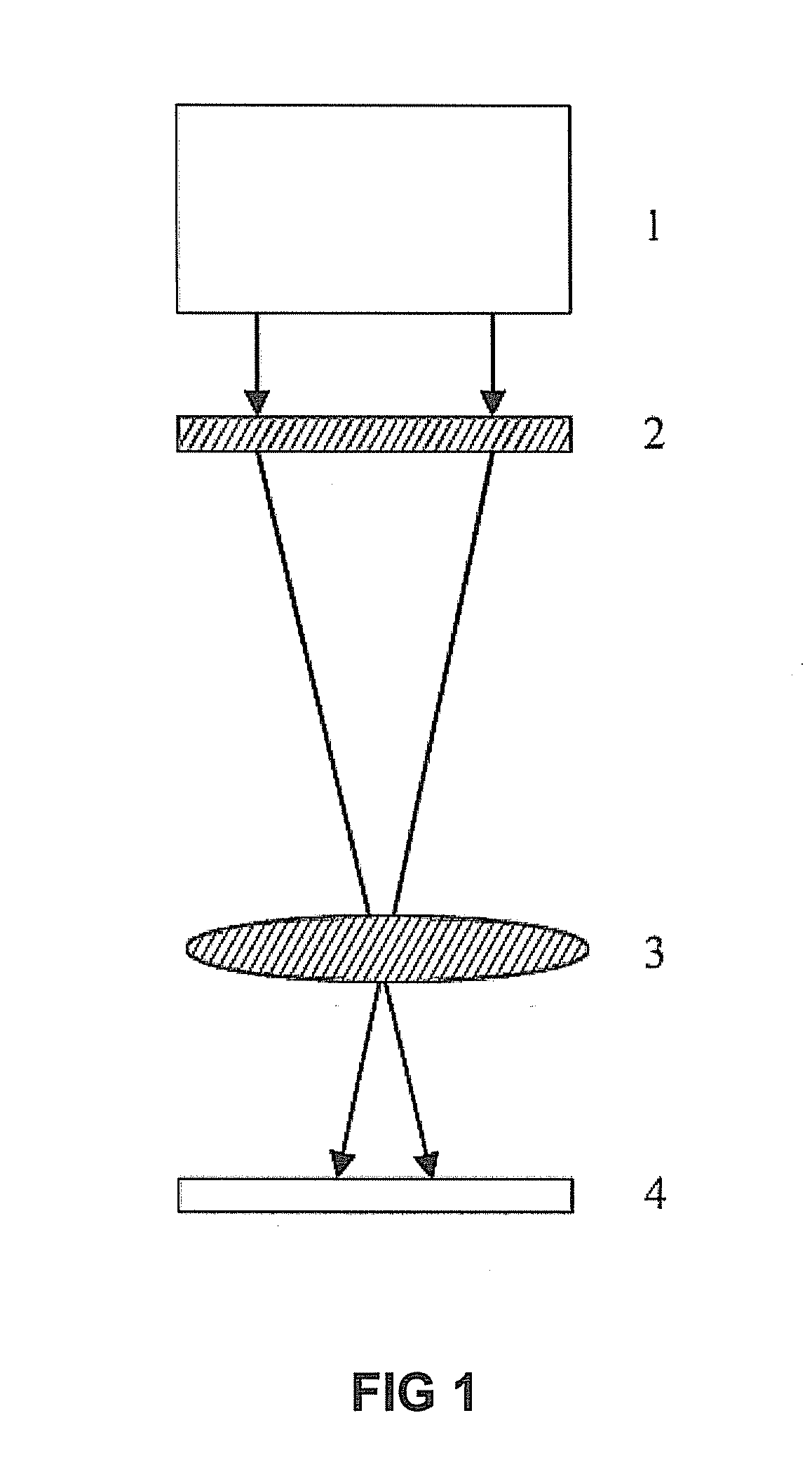
FIELD OF THE INVENTION[0001]The present disclosure relates to the field of micro-nano fabrication, and specifically relates to a projection-type photolithography system using a composite photon sieve.BACKGROUND OF THE INVENTION[0002]Projection-type photolithography systems are widely used in current integrated circuit manufacturing processes, wherein a size-reduced image of a pattern on a mask plate is projected on a substrate surface using a projection objective lens and then the pattern is transferred by means of other processing steps. A core structure of an existing projection-type photolithography system is shown in FIG. 1, comprising a lighting system 1, a mask plate 2, a projection objective lens 3, and a substrate 4. The lighting system 1 is located at the top of the system, and functions as an incident light source of high quality. The mask plate 2 is located below the lighting system 1, and provides an object to be imaged by the projection objective lens. The projection ob...

Claims


Application Information

Patent Timeline
Patent Type & Authority Applications(United States)
IPC IPC(8): G03B27/32
CPCG02B5/1876G03F7/70325G03F7/70316
Inventor XIE, CHANGQINGGAO, NANHUA, YILEIZHU, XIAOLILI, HAILIANGSHI, LINALI, DONGMEILIU, MING
Owner INST OF MICROELECTRONICS CHINESE ACAD OF SCI
Learn More