Methods and systems for treating liquids using switchable solvents

Active Publication Date: 2013-02-28
BATTELLE ENERGY ALLIANCE LLC
View PDF1 Cites 35 Cited by
  • Summary
  • Abstract
  • Description
  • Claims
  • Application Information

AI Technical Summary

Benefits of technology

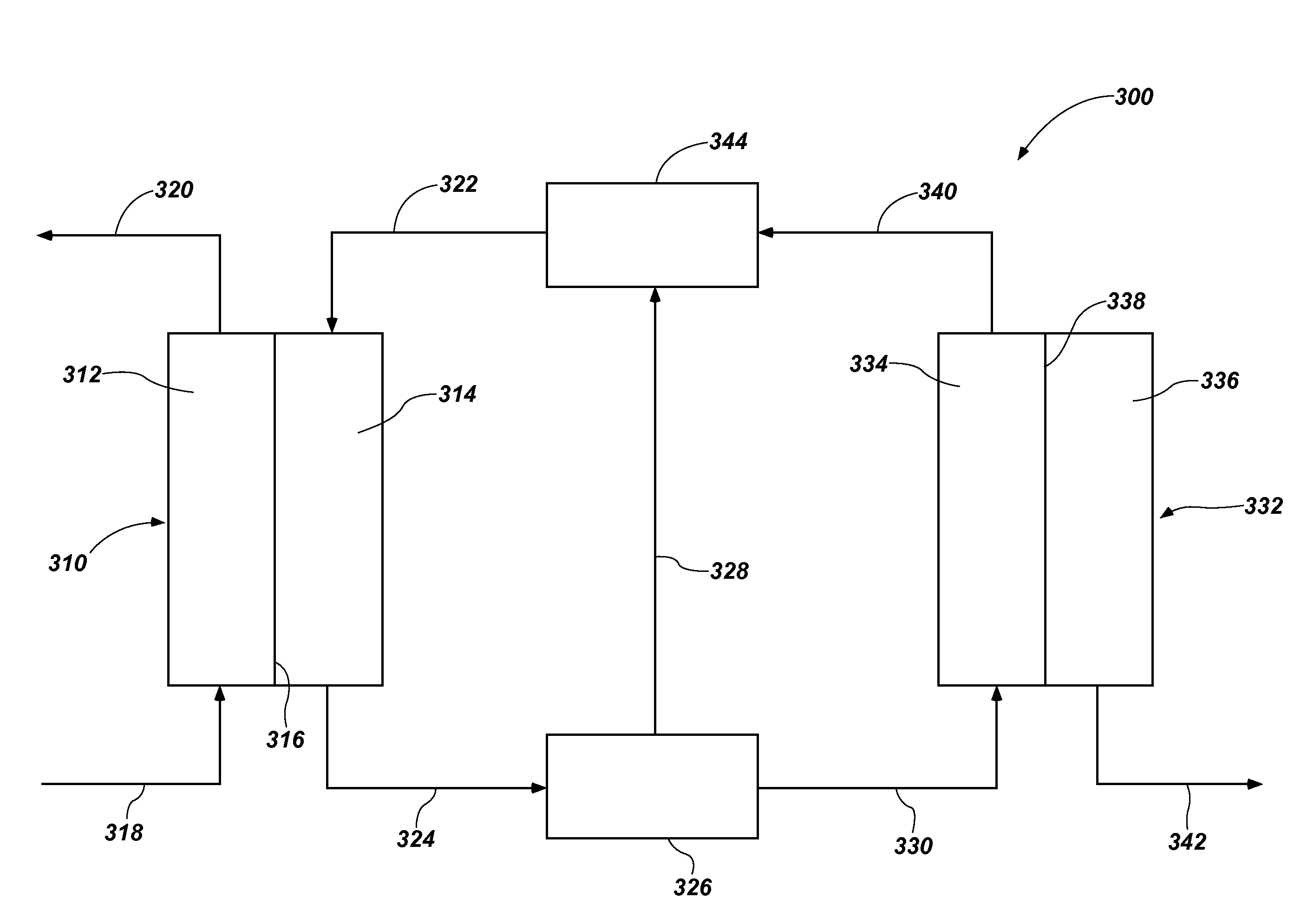
[0016]Methods and systems for treating a liquid to purify or concentrate at least one of a solvent and a solute therein using a switchable hydrophilicity solvent (SHS) are disclosed. As used herein, the term “switchable hydrophilicity solvent” means and includes a material that is configured to switch or convert from a hydrophobic form to a hydrophilic form or from a hydrophilic form to a hydrophobic form when subjected to a change in reaction conditions (e.g., the addition or removal of a gas). The hydrophobic form and hydrophilic faun of the SHS each have a different solubility in a solvent, such as water. The hydrophilic form may be miscible in the solvent, while the hydrophobic form may be immiscible in the solvent. The SHS may be used as a draw solute to separate or remove a solvent from a feed liquid by forward osmosis or to increase a concentration of at least one solute in the feed liquid. The draw solution including the SHS may have a greater osmotic pressure than the feed liquid, facilitating an osmotic pressure gradient through a semi-permeable membrane to draw the solvent into the draw solution while leaving at least one solute in the feed liquid. The solute may be a contaminant (e.g., impurit

Problems solved by technology

For water desalination processes, the pressure to overcome the osmotic pressure of the feed liquid can be substantial, such as greater than 50 atm, resulting in significant equipment and energy costs.
Additionally, the application of pressure often exacerbates reverse osmosis membrane fouling by ino

Method used


Image

  • Methods and systems for treating liquids using switchable solvents
  • Methods and systems for treating liquids using switchable solvents
  • Methods and systems for treating liquids using switchable solvents

Examples


example 1

[0054]The osmotic pressure of an aqueous solution including 59 weight percent cyclohexyldimethylaminium bicarbonate (7.6 molal) was extrapolated to be about 13.3 Osm / kg (325 atm) of osmotic pressure. By way of comparison, a simulated ocean water solution including 3.5 weight percent dissolved solids had an osmotic pressure of about 27 atm or about 1.0 Osm / Kg. This extrapolation is achieved by extending the linear relationship in osmolality dependence on the concentration of the cyclohexyldimethylaminium bicarbonate from concentrations between 0.09 and 1.81 molal. The osmolalities were found through freezing depression experiments on an osmometer. The correlation between freezing point depression, osmolality, and osmotic pressure is well established. A graphical representation of the osmolality data for of aqueous cyclohexyldimethylaminium bicarbonate solutions at different cyclohexyldimethylaminium bicarbonate concentrations is shown in FIG. 4

example 2

[0055]Aqueous saline solutions including house deionized water and varied concentrations of sodium chloride were separately provided on first sides of Hydration Technology Innovations (HTI) cartridge membranes, with aqueous draw solutions having an initial concentration of 7.6 molal cyclohexyldimethylaminium bicarbonate provided on second sides of the HTI cartridge membranes. The aqueous saline solutions and the aqueous draw solutions were each maintained at a temperature of about 30° C. An osmotic pressure differential across each of the HTI cartridge membranes generated a flow of the house deionized water from the first side of each of the membranes, across each of the membranes, and to the second side of each of the membranes. During each test, flux was allowed to stabilize over a period of from about one minute to about three minutes, and flux during a subsequent ten minute period was averaged to determine the initial flux of the system. A graphical representation of flux agains...

example 3

[0056]Cyclohexyldimethylamine (68.4 g) was added to deionized water (4.095) kg and stirred overnight to form a homogenous 16.7 g / L solution. This solution was nm through a RO unit containing a polyamide thin-film composite membrane. During the 4 hr experiment 3.925 kg of purified water was produced, divided into 17 samples of approximately 231 g each. The feed solution became torpid when the RO process was begun and an organic layer formed within the removal of the first 200 g of liquid. When the separation was complete the remaining feed solution and first wash of the system contained organic layers totaling 67.5 ml (59.4 g). On average the purified water contained less than 0.06 g / L cyclohexyldimethylamine measured by the GC FID and the concentration did not significantly increase or decrease during the course of the experiment. This is a 99.65% rejection rate of the dissolved cyclohexyldimethylamine.


PUM

PropertyMeasurementUnit
Pressureaaaaaaaaaa
Concentrationaaaaaaaaaa
Ratioaaaaaaaaaa

Abstract

A method of treating a liquid. The method comprises providing a feed liquid comprising at least one solvent and at least one solute to a first side of a membrane. A single-phase draw solution comprising at least one of an aminium salt, an amidinium salt, and a guanidinium salt is provided to a second side of the membrane. The at least one solvent is osmosed across the membrane and into the single-phase draw solution to form a diluted single-phase draw solution. At least one of CO2, CS2, and COS is removed from the diluted single-phase draw solution to form a first multiple-phase solution comprising a first liquid phase comprising the at least one solvent, and a second liquid phase comprising at least one of an amine compound, an amidine compound, and a guanidine compound. A liquid purification system is also described.

Description

CROSS-REFERENCE TO RELATED APPLICATIONS[0001]This application claims the benefit of U.S. Provisional Patent Application Ser. No. 61 / 527,944, filed Aug. 26, 2011, the disclosure of which is hereby incorporated herein in its entirety by this reference.STATEMENT REGARDING FEDERALLY SPONSORED RESEARCH OR DEVELOPMENT[0002]This invention was made with government support under Contract Number DE-AC07-05ID14517 awarded by the United States Department of Energy. The government has certain rights in the invention.TECHNICAL FIELD[0003]The present disclosure, in various embodiments, relates to methods and systems for treating a liquid to purify or concentrate at least one of a solvent and a solute therein. More specifically, embodiments of the present disclosure relate to methods and systems of treating a liquid using a switchable solvent as a draw solute.BACKGROUND[0004]Decreasing water supplies throughout much of the industrialized world necessitate new methods and systems for utilizing water...

Claims


Application Information

Patent Timeline
IPC IPC(8): B01D61/58B01D11/04C02F1/44
CPCB01D61/002B01D61/005C02F1/441A61L9/16C02F2103/06C02F2103/08C02F1/445B01D61/58B01D2311/06B01D2311/103B01D2311/25B01D2311/2642B01D2311/2653B01D2311/2661B01D61/0022B01D61/0023
Inventor WILSON, AARON D.STEWART, FREDERICK F.STONE, MARK L.
Owner BATTELLE ENERGY ALLIANCE LLC
Why Eureka
Try Eureka