

Mass spectrometer and mass analyzing method
a mass spectrometer and mass analysis technology, applied in the field of mass spectrometers, can solve the problems of poor throughput and electric power for heating, and achieve the effect of efficient ionizing a sample and less carry-over
- Summary
- Abstract
- Description
- Claims
- Application Information
AI Technical Summary
Benefits of technology
Problems solved by technology
Method used
Image

Examples
first embodiment
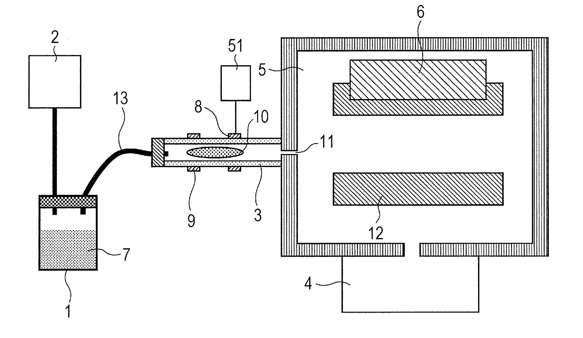
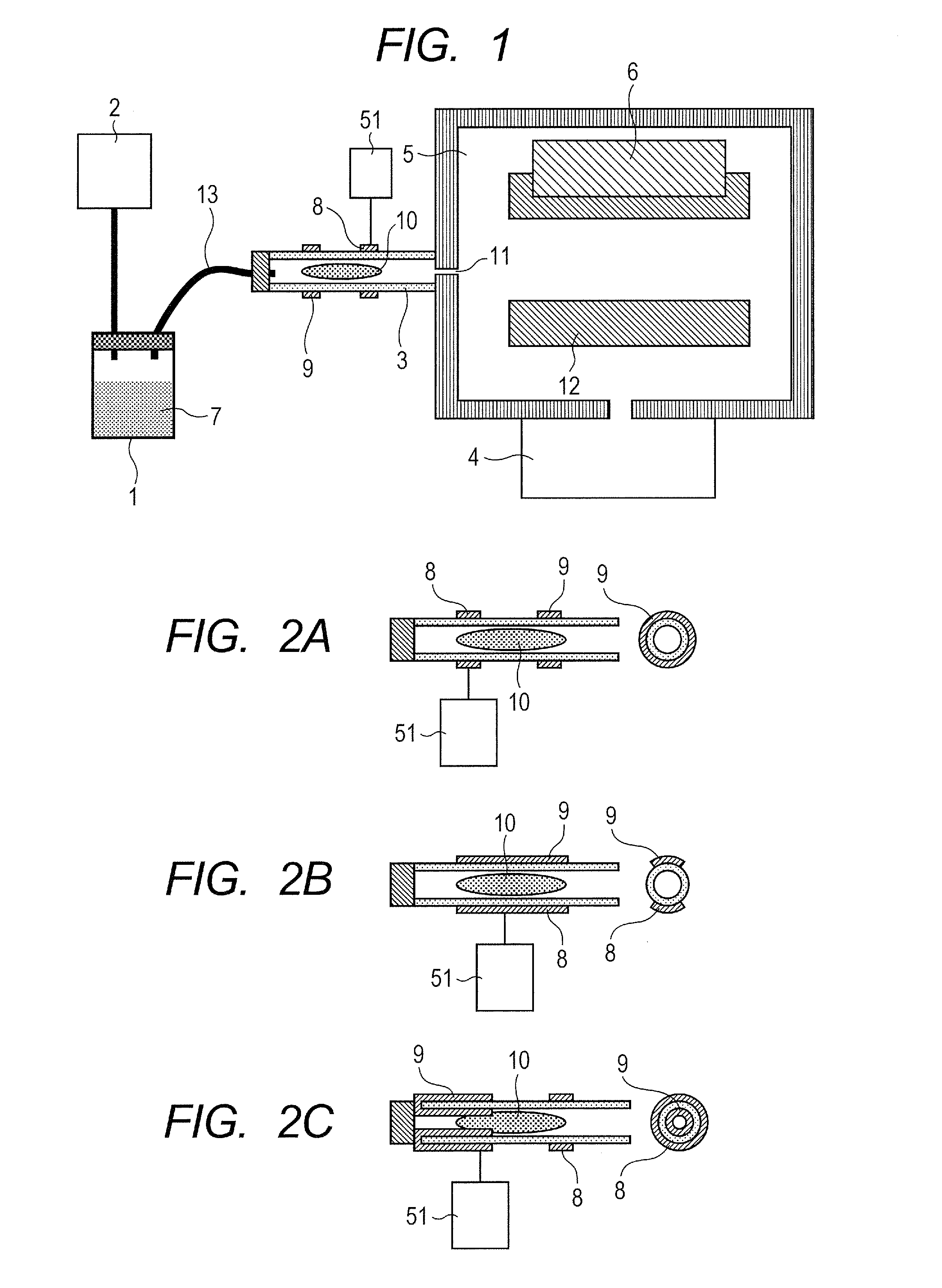
[0037]FIG. 1 is a configurational view showing an embodiment of a mass spectrometer according to the invention. The mass spectrometer mainly includes a vial bottle 1 for containing a sample 7, a pump 2 for decreasing the pressure inside of the vial bottle 1 and, in addition, an ionization housing 3 formed of a dielectric substance such as glass, plastic, ceramic, resin, or the like, and a vacuum chamber 5 kept at a pressure of 0.1 Pa or lower by a vacuum pump 4. A typical ionization housing is a tube having an outer diameter of about 4 mm and an inner diameter of about 1 to 4 mm. While the vial bottle 1 and the ionization housing 3 are connected by way of a sample transfer line in FIG. 1, they may be also connected not by the sample transfer line but by way of an orifice so long as the pressure condition as to be described later can be maintained.
[0038]The sample 7 may be liquid or solid. The pressure inside of the vial bottle 1 is decreased by the pump 2. The pressure inside the va...
second embodiment
[0049]FIG. 6 is a configurational view showing an embodiment of a mass spectrometer according to the invention. The pressure condition for a plasma 10 and the output voltage from a power source 51 are identical with those of the first embodiment.
[0050]Different from the first embodiment, a pulse valve 30 is interposed between an ionization housing 3 and a vial bottle 1, and a gas is introduced discontinuously into the ionization housing 3. Upon introduction of the gas, the pressure in the ionization housing 3 increases temporality, and the pressure in the ionization housing 3 is lowered when the pulse valve 30 is closed. Accordingly, compared with the continuous gas introduction system of the first embodiment, even when the inner diameter of the orifice 11 is increased to increase the flow rate of the gas introduced into the vacuum chamber 5, the pressure in the vacuum chamber 5 can be maintained to 0.1 Pa or lower after closing the pulse valve 30. Since the headspace gas does not f...
third embodiment
[0055]FIG. 9 is a configurational view showing an embodiment of the mass spectrometer according to the invention. The pressure condition for a plasma 10 and the output voltage of a power source 51 are identical with those of the first embodiment. Different from the first and second embodiments, a pump 2 for the vial bottle is connected not to the vial bottle 1 but to the tube 13. In the same manner as in the first and second embodiments, the pressure inside of vial bottle 1 is decreased and the ratio of the sample in the headspace gas is increased. Since the number of the sample transfer lines connected to the vial bottle 1 is decreased to one, the configuration of the vial bottle 1 is simplified and decrease in the cost is expected. On the other hand, since a fresh gas always flows continuously in the tube 13, it has a drawback that adsorption becomes remarkable
[0056]The heater 14 for heating the vial bottle 1 shown in the first embodiment is applicable also in this embodiment.
PUM
 Abstract
Description
Claims
Application Information