Vehicular starter ring gear
a starter ring and ring gear technology, applied in the direction of engine starters, machine/engines, gears, etc., can solve the problems of circumferential local wear of external teeth, reduced hardness of some external teeth, etc., to reduce the degree of annealing of external teeth, restrain the conduction of heat, and restrain the reduction of hardness of external teeth
- Summary
- Abstract
- Description
- Claims
- Application Information
AI Technical Summary
Benefits of technology
Problems solved by technology
Method used
Image
Examples
first embodiment
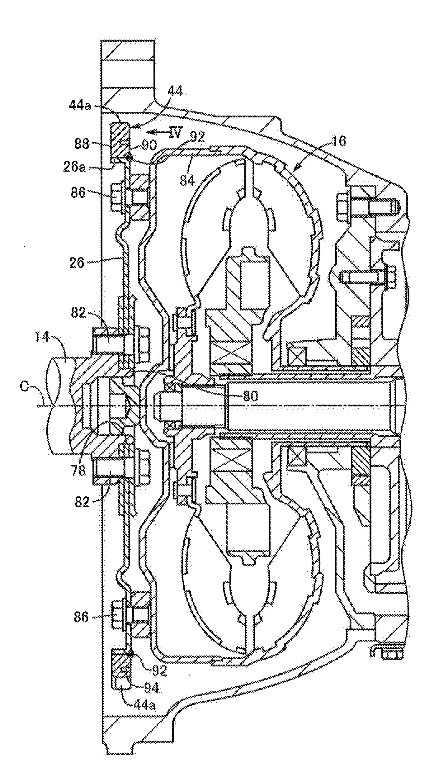
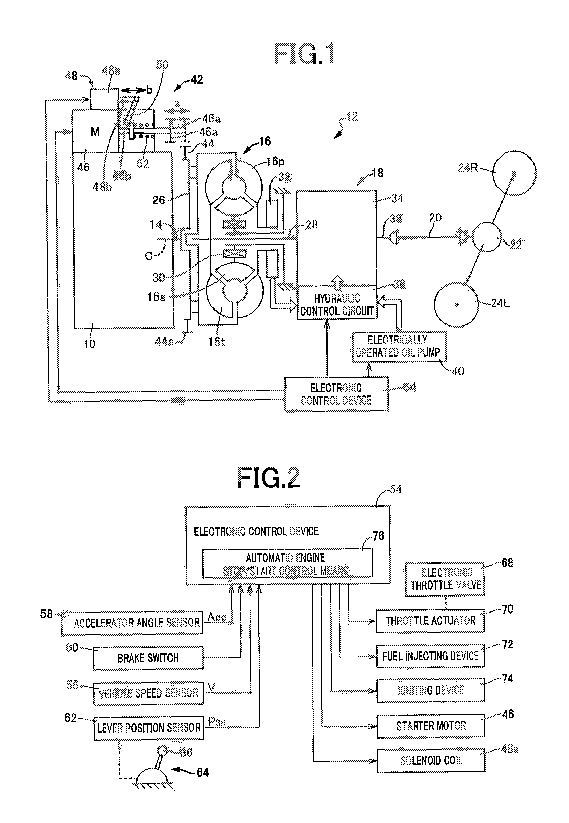
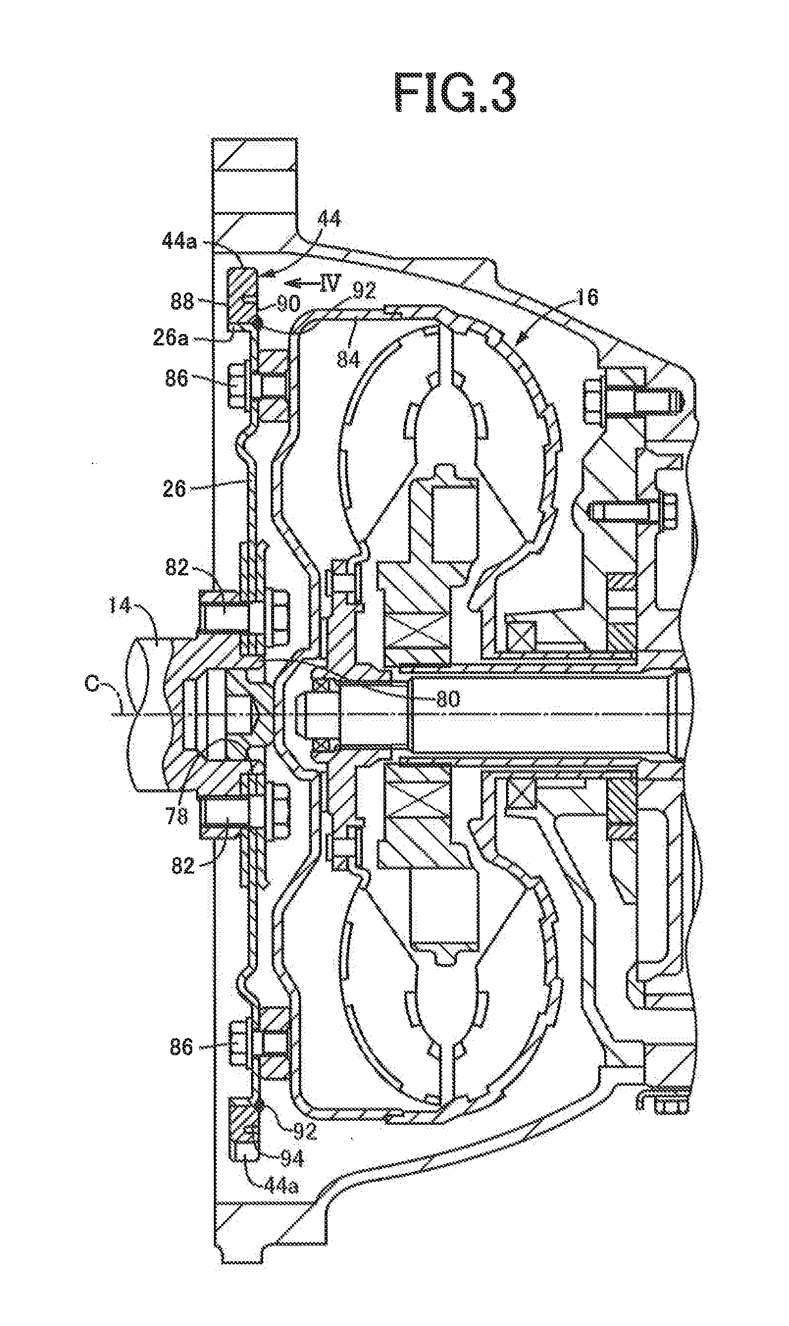
[0033]FIG. 1 is the schematic view showing the arrangements of an engine 10 and a power transmitting system 12 of a vehicle to which the present invention is applicable. These engine 10 and power transmitting system 12 are suitably used for a FR (front-engine rear-drive) vehicle. An output of the engine 10 in the form of an internal combustion engine serving as a vehicle drive power source is transmitted from a crankshaft 14 of the engine 10 to a differential gear device 22 through a torque converter 16, an automatic transmission 18 and a propeller shaft 20, and is distributed from the differential gear device 22 to left and right drive wheels 24L, 24R.
[0034]The torque converter 16 is provided with: a pump impeller 16p connected to the crankshaft 14 through a driving plate 26 in the form of a disc; a turbine impeller 16t connected to an input shaft 28 of the automatic transmission 18; and a stator impeller 16s which is prevented by an one-way clutch 30 from rotating in one direction...
second embodiment
[0055]Other embodiments of this invention will be described. In the following descriptions, the same reference signs will be used to identify the same elements of the different embodiments, which will not be described.
[0056]FIG. 7 is the view corresponding to that of FIG. 4 of the first embodiment, and showing a starter ring gear 100 according to another embodiment of the invention, and the driving plate 26. As shown in FIG. 7, the starter ring gear 100 is identical with the starter ring gear 44 of the first embodiment, except in that the arcuate grooves 94 are replaced by an annular groove 102 formed in a radial portion of the side surface 90 between the inner circumferential surface and the peak surfaces of the external teeth 44a of the starter ring gear 100, and radially outwardly of the plurality of welding portions in the form of weld beads 92 between the starter ring gear 100 and the driving plate 26, such that the annular groove 102 is formed continuously over the entire circ...
third embodiment
[0060]FIG. 8 is the view corresponding to that of FIG. 5 showing the first embodiment, and showing a starter ring gear 110 according to a further embodiment of the invention, and the driving plate 26. As shown in FIG. 8, the starter ring gear 110 is identical with the starter ring gear 44 of the first embodiment, except in that the arcuate grooves 94 are replaced by a plurality of (four in this embodiment) through-holes 112 formed in a radial portion between the inner circumferential surface and the peak surfaces of the external teeth 44a of the starter ring gear 110, so as to extend between its opposite side surfaces 88, 90, and radially outwardly of the plurality of welding portions in the form of weld beads 92 between the starter ring gear 110 and the driving plate 26, such that the through-holes 112 have a circumferential length larger than that of the weld beads 92. The circumferential positions at which these through-holes 112 are formed are the same as those of the arcuate gr...
PUM
| Property | Measurement | Unit |
|---|---|---|
| thickness | aaaaa | aaaaa |
| circumference | aaaaa | aaaaa |
| hardness | aaaaa | aaaaa |
Abstract
Description
Claims
Application Information
 - R&D
- Intellectual Property
- Life Sciences
- Materials
- Tech Scout
- Unparalleled Data Quality
- Higher Quality Content
- 60% Fewer Hallucinations
Browse by: Latest US Patents, China's latest patents, Technical Efficacy Thesaurus, Application Domain, Technology Topic, Popular Technical Reports.
© 2025 PatSnap. All rights reserved.Legal|Privacy policy|Modern Slavery Act Transparency Statement|Sitemap|About US| Contact US: help@patsnap.com


