Electrode, electrically heating type catalyst device using same, and manufacturing method of electrically heating type catalyst device

a manufacturing method and catalyst technology, applied in the direction of heat exchangers, machines/engines, mechanical devices, etc., can solve the problems of cracking and/or peeling of electrodes, and achieve the effect of minimizing the increase in electrical resistan

Active Publication Date: 2013-03-14
TOYOTA JIDOSHA KK
View PDF3 Cites 11 Cited by
  • Summary
  • Abstract
  • Description
  • Claims
  • Application Information

AI Technical Summary

Benefits of technology

[0045]According to the present invention, it is possible to provide an electrode capable of

Problems solved by technology

It should be noted that there has been a problem that cracking and/or peeling occur in the electrode because of the difference between the

Method used


Image

  • Electrode, electrically heating type catalyst device using same, and manufacturing method of electrically heating type catalyst device
  • Electrode, electrically heating type catalyst device using same, and manufacturing method of electrically heating type catalyst device
  • Electrode, electrically heating type catalyst device using same, and manufacturing method of electrically heating type catalyst device

Examples


first exemplary embodiment

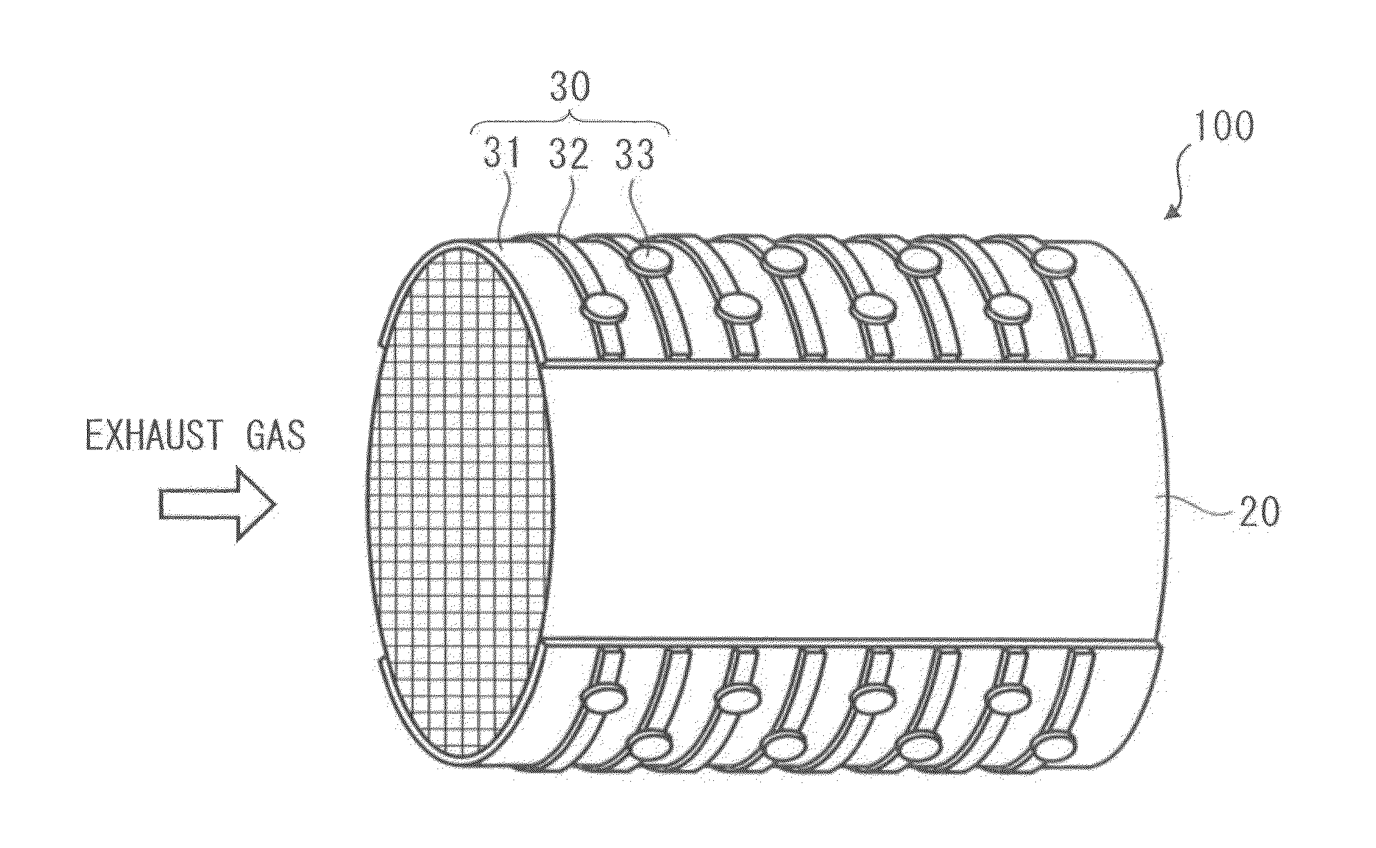
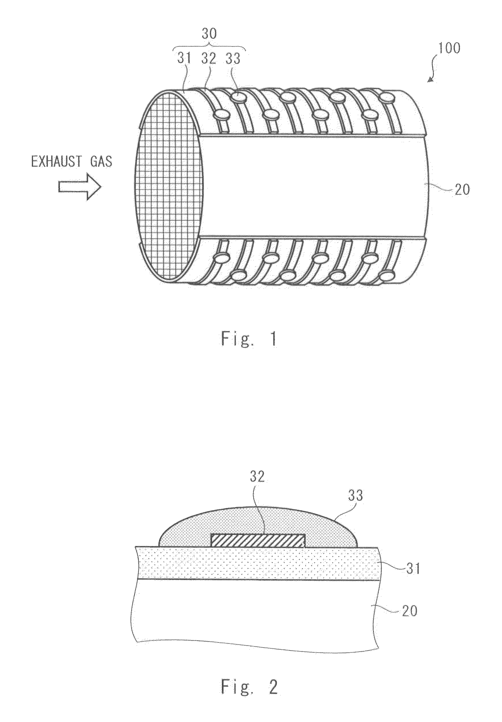
[0065]Firstly, an electrically heating catalyst device according to this exemplary embodiment is explained with reference to FIGS. 1 and 2. FIG. 1 is a perspective view of an electrically heating catalyst device 100 according to a first exemplary embodiment. The electrically heating catalyst device 100 is provided, for example, on a discharge path of an automobile or the like, and purifies an exhaust gas discharged from the engine. As shown in FIG. 1, the electrically heating catalyst device 100 includes a catalyst support 20 and electrodes 30.

[0066]The catalyst support 20 is a porous member on which a catalyst such as platinum and palladium is supported. Further, since the catalyst support 20 itself is electrically heated, the catalyst support 20 is composed of a conductive ceramics, for example, SiC (silicon carbide). As shown in FIG. 1, the catalyst support 20 has a cylindrical external shape and has a honeycomb structure inside thereof. As indicated by an arrow, an exhaust gas p...

example 1

[0102]Matrix particles having a particle diameter of 10 to 50 μm (average particle diameter 30 μm), composed of Ni-50 wt. % Cr alloy, which was used to form the metal matrix, were produced by using a gas atomizing method.

[0103]Meanwhile, disperse-phase particles having a particle diameter of 10 to 50 μm (average particle diameter 30 μm), composed of bentonite, which was used to form the disperse phase, were produced by using a spray-dry method. These particles were sintered at a temperature of 1050° C. in a hydrogen atmosphere.

[0104]Next, the matrix particles and the disperse-phase particles were formed a composite by using a kneading particle-producing method while using a polymer adhesive as a medium. Further, the composite particles were sintered at a temperature of 1050° C. in a hydrogen atmosphere. As a result, particles for thermal spraying were produced.

[0105]Next, the above-described disperse-phase particles were plasma-sprayed on the surface of a catalyst support 20 compose...

example 2

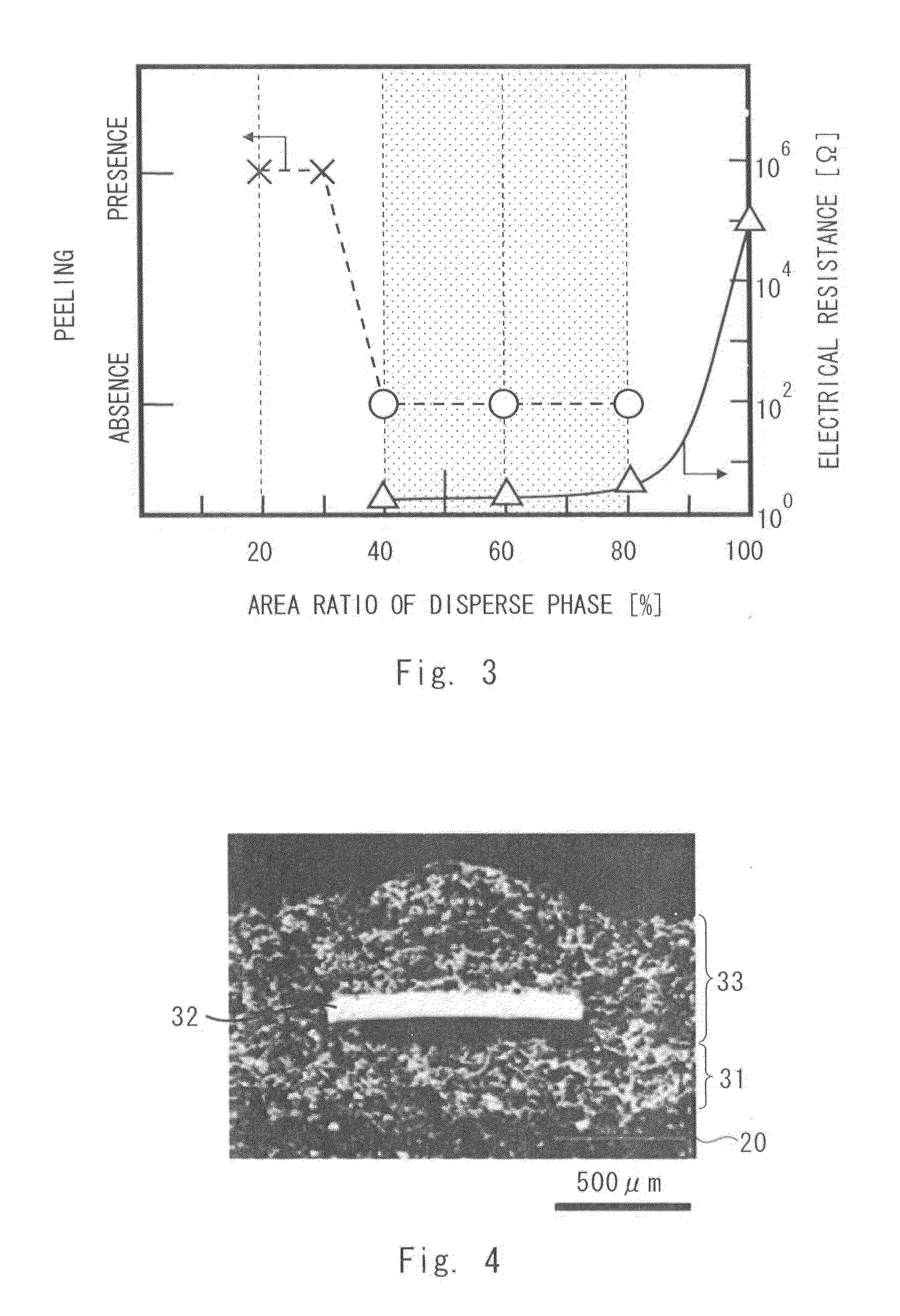
[0109]A thermal-sprayed film was formed in the same manner as that of Example 1 except that the area ratio of the disperse phase was adjusted to 60%. As a result, the electrical resistance measured after the thermal cycles was 2.8Ω and was extremely excellent result. FIG. 16 is a photograph of a cross-sectional structure of a thermal-sprayed film according to Example 2.


PUM

PropertyMeasurementUnit
Fractionaaaaaaaaaa
Particle diameteraaaaaaaaaa
Pressureaaaaaaaaaa

Abstract

An electrode according to one aspect of the present invention is formed on a base material composed of a ceramics. The electrodes includes a matrix composed of an Ni-Cr alloy (with a Cr content of 20 to 60 wt. %) or an MCrAlY alloy (M is at least one material selected from Fe, Co and Ni), and a disperse phase that is dispersed in the matrix and composed of an oxide mineral having a laminated structure. The ratio of area occupied by the disperse phase in a cross section of the electrode is 40 to 80%. With the structure like this, it is possible to suppress the increase in the electrical resistance even after a thermal cycle is performed.

Description

TECHNICAL FIELD[0001]The present invention relates to an electrode, an electrically heating type catalyst device using the electrode, and a manufacturing method of an electrically heating type catalyst device.BACKGROUND ART[0002]In recent years, EHCs (electrically heated catalysts) are attracting attention as an exhaust purification device that purifies exhaust gases discharged from engines of automobiles and the like. In EHCs, it is possible to forcibly activate a catalyst by electrical heating even under such conditions that the temperature of the exhaust gas is low and thus the catalyst cannot be easily activated, such as immediately after the engine is started, and thereby to enhance the purification efficiency of the exhaust gas.[0003]An EHC disclosed in Patent literature 1 includes a cylindrical catalyst support having a honeycomb structure on which a catalyst such as platinum and palladium is supported, and a pair of electrodes that are electrically connected to the catalyst ...

Claims


Application Information

Patent Timeline
IPC IPC(8): H05B3/02C23C4/12
CPCH05B2203/024H05B2203/022H05B3/42H05B3/08F01N3/20H05B3/03
Inventor SHIMODA, KENJINISHIO, KAZUAKIKINOSHITA, YASUOTAKAGAKI, TADASHI
Owner TOYOTA JIDOSHA KK
Why Eureka
Try Eureka