
Method for Reliably Soldering Microwave Dielectric Ceramics with Metal

a microwave dielectric ceramic and reliably soldering technology, applied in the field of soldering, can solve the problems of ceramic breakage, relatively narrow application scope, and inability to reliably solder ultrahigh metal cavities, and achieve the effect of saving soldering cost and improving environmental reliability of soldered structural components

Inactive Publication Date: 2013-03-14
CHENGDU TIGER MICROWAVE TECH
View PDF5 Cites 4 Cited by
  • Summary
  • Abstract
  • Description
  • Claims
  • Application Information

AI Technical Summary

Benefits of technology

The present invention provides a method for reliably soldering microwave dielectric ceramics with metal using a strict process of heating up, soldering under heat preservation, and cooling. This method reduces thermal stress, ensures reliability of the solder structure, decreases porosity, improves soldering quality, and reduces soldering cost. It can meet the demand of large-scale production in the field of civil communication. The invention adopts a brand-new soldering tool and utilizes vapor soldering and perfluoropolyether liquid for heating and cooling.

Problems solved by technology

(1) The total hot-air reflow soldering machine is mainly featured by soldering of surface-mounted devices and its internal working area is not high, so soldering is unavailable for ultrahigh metal cavity, and its applicable scope is relatively narrow.
(2) The convection of hot air will be hindered owing to the presence of sidewalls of the inner cavity of filter. The temperature inside the cavity of filter becomes uneven, and thus thermal stress is generated inside the microwave dielectric ceramics to result directly in ceramic breakage and cause a severe impact to soldering quality.
(3) Soldering quality is affected by large property differences between the aluminum-made cavity 13 of filter and the microwave dielectric ceramic material. For example, there is large difference between the aluminum-made cavity 13 of filter and the microwave dielectric ceramic material in the aspect of coefficient of thermal expansion, so the soldering side is liable to be torn after strict environmental temperature shock to further lead to soldering failure.
Secondly, the heat conductivity of the aluminum-made cavity 13 of filter is far more than that of the ceramics, so its heating and cooling are faster, and strict controls for identical heating and cooling of the aluminum-made cavity 13 and the ceramics would induce very long soldering procedure and remarkable increase of soldering cost.
(4) In order to prevent silver-plated surface from being oxidized at high temperature, inert gases, such as nitrogen, are required in current reflow soldering, which also raises soldering cost correspondingly.
(5) There is no vent hole on the soldering surface of metal, which could cause uneven discharge of gases in the solder paste and further give rise to poor soldering. In this case, the structural reliability of the soldered component is negatively affected.
(6) Due to the huge difference between ceramics and metal cavity in the expansion coefficient, the soldered component of both couldn't pass the strict test on temperature reliability of products even if, it is successfully soldered by the total hot-air reflow soldering machine.

Method used


Image

  • Method for Reliably Soldering Microwave Dielectric Ceramics with Metal
  • Method for Reliably Soldering Microwave Dielectric Ceramics with Metal
  • Method for Reliably Soldering Microwave Dielectric Ceramics with Metal

Examples


embodiment 1

[0037]As shown in FIG. 1 and FIG. 2, a method for reliably soldering microwave dielectric ceramics with metal comprises the following steps of:

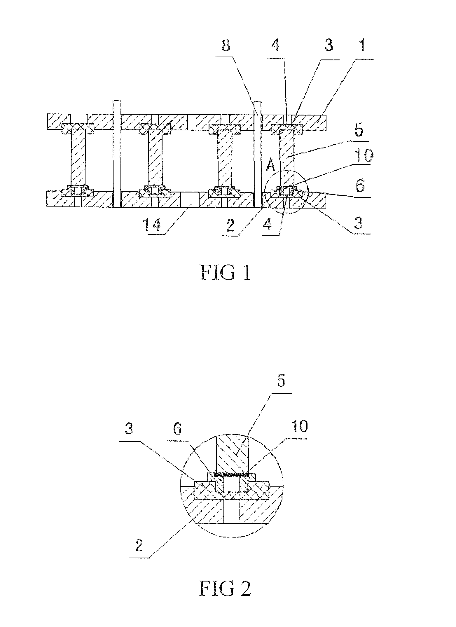
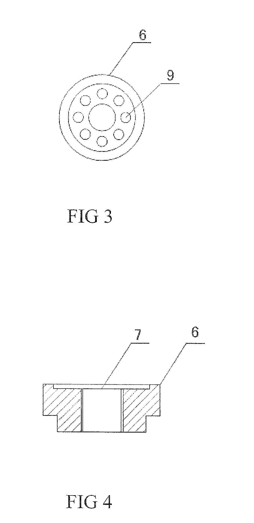
[0038](1) uniformly coating a layer of lead-free solder paste 10 on a silver-plated end face 6 of microwave dielectric ceramics 5 and fixing the microwave dielectric ceramics on a positioning groove 7 of a silver-plated metal base 6, then placing the microwave dielectric ceramics and the silver-plated metal base, as a whole, in notches 4 of an upper positioning plate 1 and a lower positioning plate 2, and clamping and fixing the upper positioning plate 1 and the lower positioning plate 2 through a positioning pin 8 to form a component to be soldered;

[0039](2) putting the component to be soldered in a sealed container filled with perfluoropolyether liquid;

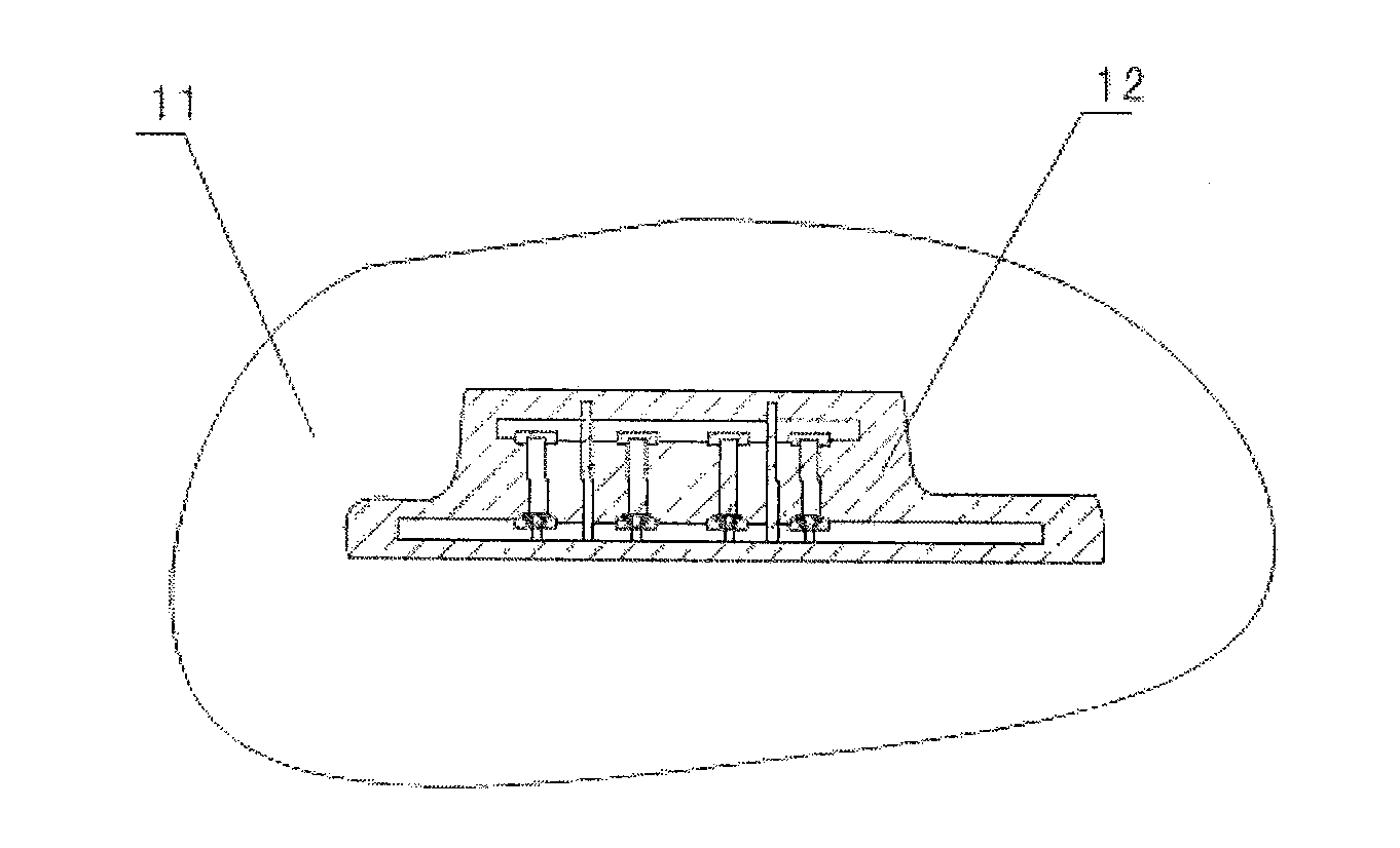
[0040](3) heating the perfluoropolyether liquid at the rate of 0.5° C. / sec until uniform perfluoropolyether vapor 11 is formed;

[0041](4) preserving heat for 2 minutes until the temperature of...

embodiment 2

[0043]A method for reliably soldering microwave dielectric ceramics with metal comprises the steps 1 and 2 same as those in the above embodiment 1 and further comprises the steps of:

[0044](3) heating the perfluoropolyether liquid at the rate of 3° C. / sec until uniform perfluoropolyether vapor 11 is formed;

[0045](4) preserving heat for 0.5 minutes until the temperature of the component to be soldered is identical to that of the vapor, wherein in this process, the perfluoropolyether vapor 11 is subjected to heat exchange with a contact face of the silver-plated end face 6 and the microwave dielectric ceramics 5 and a liquid film 12 is formed, thus the lead-free solder paste 10 covered by the liquid film 12 is molten to form a soldering side; and

[0046](5) cooling at the rate of 3° C. / sec.

embodiment 3

[0047]A method for reliably soldering microwave dielectric ceramics with metal comprises the steps 1 and 2 same as those in the above embodiment 1 and further comprises the steps of:

[0048](3) heating the perfluoropolyether liquid at the rate of 2° C. / sec until uniform perfluoropolyether vapor 11 is formed;

[0049](4) preserving heat for 1 minute until the temperature of the component to be soldered is identical to that of the vapor, wherein in this process, the perfluoropolyether vapor 11 is subjected to heat exchange with a contact face of the silver-plated end face 6 and the microwave dielectric ceramics 5 and a liquid film 12 is formed, thus the lead-free solder paste 10 covered by the liquid film 12 is molten to form a soldering side; and

[0050](5) cooling at the rate of 2° C. / sec.


PUM

PropertyMeasurementUnit
microwave dielectricaaaaaaaaaa
temperatureaaaaaaaaaa
insulatingaaaaaaaaaa

Abstract

A method for reliably soldering microwave dielectric ceramics with metal adopting the way of vapor soldering, a strict process of heating up, then soldering under heat preservation and finally cooling is provided. Therefore, thermal stress generated during the soldering of dielectric ceramics and metal material is reduced, reliability of a solder structure is ensured, porosity of the soldering side is effectively lowered, soldering quality is improved, soldering cost is reduced, and the demand of large-scale production can be met.

Description

BACKGROUND OF THE PRESENT INVENTION[0001]1. Field of Invention[0002]The present invention relates to the technical field of soldering, more particularly to a method for reliably soldering microwave dielectric ceramics with metal.[0003]2. Description of Related Arts[0004]Microwave dielectric ceramics, a novel functional ceramic material that has been developed over the recent twenty years, is the ceramic material used as a dielectric material in circuit with microwave frequency (mainly in a frequency band from 300 MHz to 30 GHz) and realizing one or multiple functions, and becomes the key material for manufacturing microwave dielectric filter and resonator. Owing to excellent properties such as high dielectric coefficient, low dielectric loss and small temperature coefficient, microwave dielectric ceramics could meet the demands of microwave circuit on miniaturization, integration, high reliability and low cost. As a result, it is suitable for the manufacturing of multiple types of m...

Claims


Application Information

Patent Timeline
Patent Type & Authority Applications(United States)
IPC IPC(8): B23K1/20
CPCB23K1/0016B23K1/20B23K1/19
Inventor WANG, YINGJUN
Owner CHENGDU TIGER MICROWAVE TECH
Learn More