Method and device for two-stage solar concentration and spectrum splitting based on dish concentration

a technology of spectrum splitting and solar energy, applied in the field of solar energy, can solve the problems of reducing the photoelectric conversion efficiency, affecting the efficiency of photoelectric conversion, so as to improve the system balance and wind resistance, and reduce the energy consumption of tracking systems.

Inactive Publication Date: 2013-03-21
ZHEJIANG UNIV
View PDF4 Cites 11 Cited by
  • Summary
  • Abstract
  • Description
  • Claims
  • Application Information

AI Technical Summary

Benefits of technology

[0012]1. The method of the present invention can simultaneously realize the concentration and splitting of solar energy and obtain two concentrating spots under the system, thus effectively reducing the energy consumption of tracking system and improving system balance and wind resistance.
[0013]2. The meth

Problems solved by technology

Manufacturing PV panels cause serious pollution and incur high cost; (3) the response wave bands of PV panel to solar spectrum are mainly concentrated in high frequency area (400<λ<1100 nm).
Most of the energy in low frequency area is converted to heat to raise the temperature of PV panel, lower their photo-electric conversion efficiency and shorten their service life.
As to the discontinuity of solar radiation, PV technology can only rely on expensive supplementary accumulator battery or energy-storage generating system (such as pumped storage hydroelectric power station).
This technology can only realize one dimensional trace of the sun

Method used


Image

  • Method and device for two-stage solar concentration and spectrum splitting based on dish concentration
  • Method and device for two-stage solar concentration and spectrum splitting based on dish concentration
  • Method and device for two-stage solar concentration and spectrum splitting based on dish concentration

Examples


examples

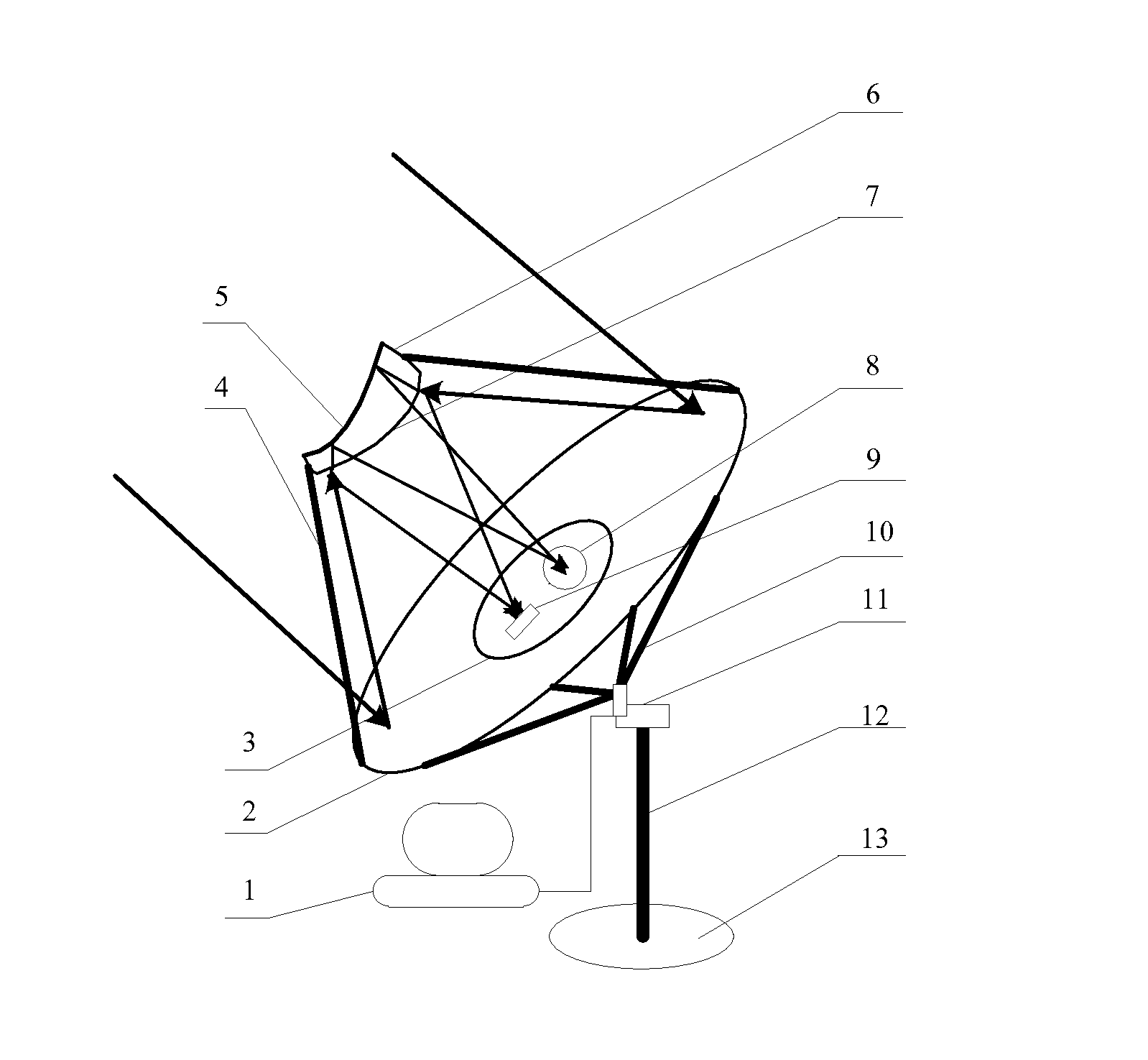
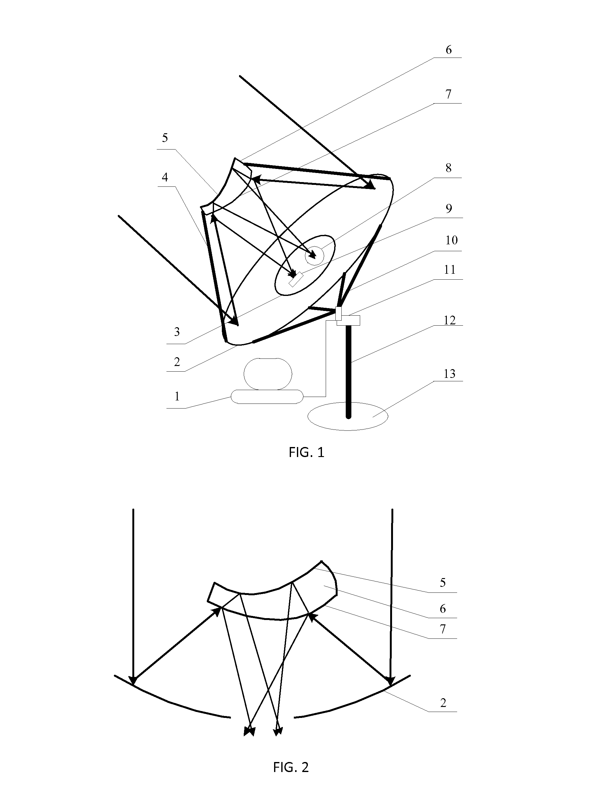
[0026]The apex of rotary parabolic reflecting surface is set as the initial point and the horizontal plane is set as the XY plane. The axis vertical to the plane is set as Z axis (Z>0). The parabolic dish has a diameter of 3500 mm and the opening of light hole has a diameter of 600 mm. The standard equation of the parabolic dish can be written as X2+Y2=6062Z. Splitting lens with a diameter of 600 mm is placed right over the central axial line of parabolic dish. The vertical distance between the center of splitting lens and the initial point is 1265 mm. The curve with splitting film will rotate 4.6° around the coordinate system, so that when the central axial line coincides with the central axial line of the parabolic dish, the standard equation of the hyperboloid can be written as

Z26632-X2+Y26602=1.

The silver covered surface will rotate 4.6° in a reverse direction around the coordinate system, so that when the central axial line coincides with the central axial line of the parabolic...


PUM


Abstract

The present invention discloses a method and device for two-stage solar concentration and a spectrum splitting dish reflector based on dish concentration. A parabolic dish reflector is provided with a central light hole. A CPV panel and a solar-to-heat receiver are positioned at the two sides of the axial line of dish reflector, respectively, under the light hole. A splitting lens is placed at a certain distance from the apex of dish reflector over the light hole. The splitting film is applied to the curved surface of the lens near the parabolic dish, as a spectrum splitting surface. The curved surface of the lens far from the parabolic dish is covered by silver, as a reflecting surface. A supporting structure is provided between the dish reflector and the splitting lens. The whole system with a dual-axis tracking system is placed on the foundation of a support. The present invention can simultaneously realize solar energy concentration and spectrum splitting, to obtain two concentrated spots of different spectrums under the system, which can effectively reduce energy consumption of tracking system and improve system balance and wind resistance. The present invention can adjust the concentration ratio of two beams individually to satisfy the optimal concentrating intensity needed by the CPV panel and the solar-to-heat receiver.

Description

FIELD OF THE INVENTION[0001]The present invention relates to the field of using solar to generate power, and more specially relates to a method and device for two-stage solar concentration and spectrum splitting.DESCRIPTION OF THE PRIOR ART[0002]The global solar radiation amount is about 1.7×10¹⁷ W, among which China holds about 1% (1.8×10¹⁵ W, equivalent to 1,900,000 million tons of standard coal per year), which is 680 times of the annual energy consumption in the whole country. Electricity is the largest secondary energy consumed in the world. The technology to use solar energy generating power is the effective way to relieve current energy crises and has a broad perspective in application.[0003]Solar power technology is mainly divided into two types: photovoltaic (PV) and solar thermal power (STP) technology. PV power technology makes use of photovoltaic effect of photovoltaic panel to generate electricity. This technology has three main shortcomings: (1) the generated output ch...

Claims


Application Information

Patent Timeline
IPC IPC(8): H01L31/058F24J2/12F24J2/38F24J2/08F24S23/30F24S23/71F24S50/20G02B7/00G02B7/198
CPCF24J2/08F24J2/12F24J2/5417F24J2/38H01L31/0549Y02E10/52Y02E10/42H01L31/0547H01L31/058F24S30/45F24S23/71F24S23/30Y02E10/47F24S50/20Y02E10/40
Inventor NI, MINGJIANGXIAO, GANGLUO, ZHONGYANGCEN, KEFAGAO, XIANGFANG, MENGXIANGZHOU, JINSONGSHI, ZHENGLUNCHENG, LEMINGWANG, QINHUIWANG, SHURONGYU, CHUNJIANG
Owner ZHEJIANG UNIV
Why Eureka
Try Eureka