Boundary Layer Disk Turbine Systems for Controlling Pneumatic Devices

a technology of pneumatic devices and disk turbines, which is applied in the direction of radial flow pumps non-positive displacement fluid engines, etc., can solve the problems of high risk of hydrocarbon emissions, high cost of production, and high environmental and public health damage,

Inactive Publication Date: 2013-03-21
LEED FABTION SERVICES
View PDF4 Cites 3 Cited by
  • Summary
  • Abstract
  • Description
  • Claims
  • Application Information

AI Technical Summary

Benefits of technology

[0044]FIG. 1 illustrates the boundary layer effect that drives a BLDT.

Problems solved by technology

In addition, loose, damaged, and worn fittings or piping in what is often a complex tube and pipe layout may also significantly contribute to fugitive emissions from the pneumatic system.
Those natural gas emissions are not only destructive to the environment and public health, but are a costly loss of potential revenue to the producer.
The health effects of hydrocarbon emissions are also considered to be highly dangerous.
Most current solutions that replace natural gas pneumatics with air pneumatics require either electric or gas-powered (natural gas or gasoline) compressors that can be very costly to purchase, operate and maintain.
Furthermore, remote drilling sites may not have electric hook-up, and running gas compressors simply replace one source of pollution with another.
Maintenance can become an issue for both electric and gas powered compressor systems, which is further compounded by sites that are not readily accessible.
For example, all the same issues exist in a multitude of facilities including plants and offshore drilling rigs.

Method used


Image

  • Boundary Layer Disk Turbine Systems for Controlling Pneumatic Devices
  • Boundary Layer Disk Turbine Systems for Controlling Pneumatic Devices
  • Boundary Layer Disk Turbine Systems for Controlling Pneumatic Devices

Examples


example 1

Disk Turbine Pneumatic Control System

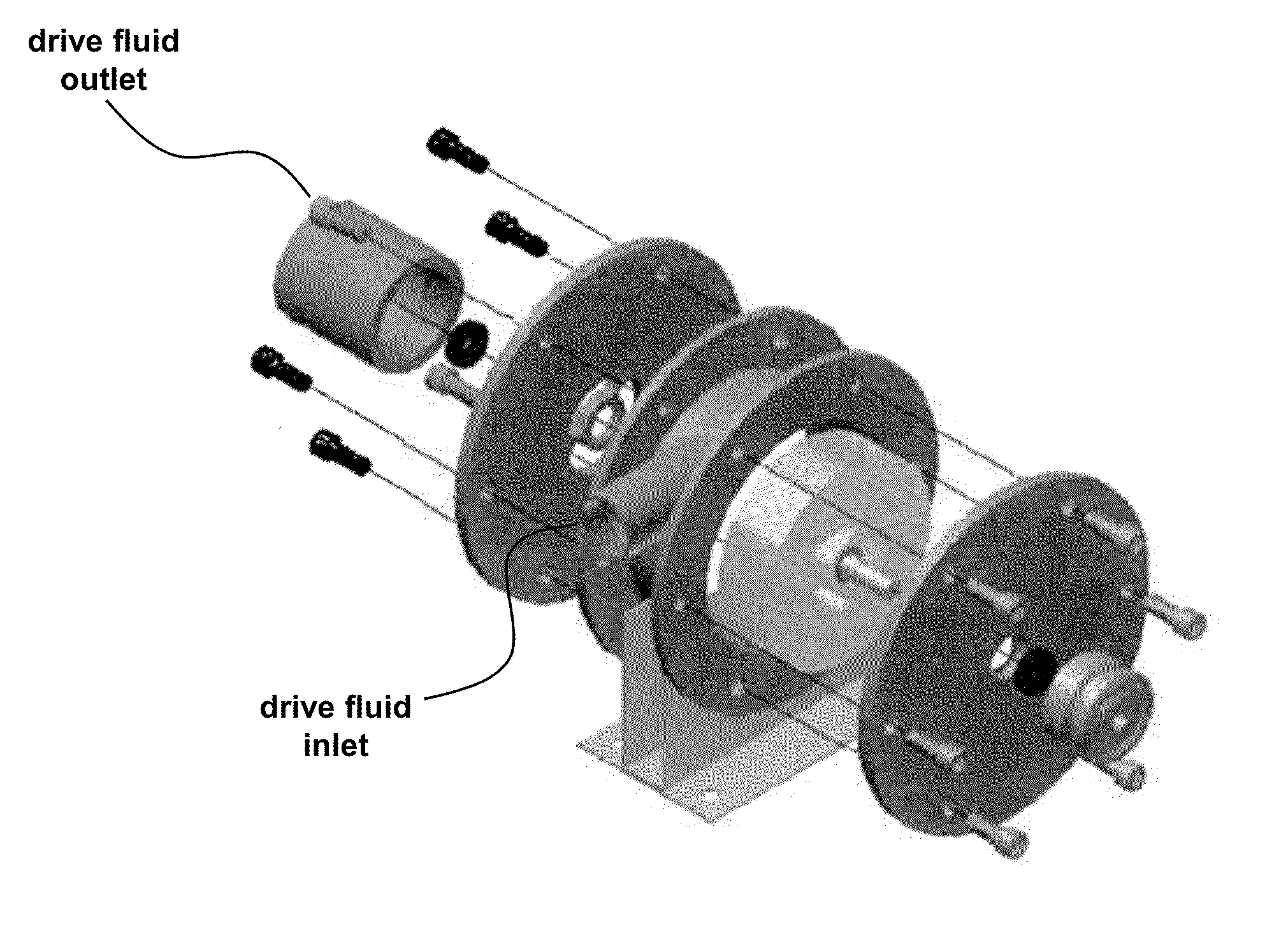
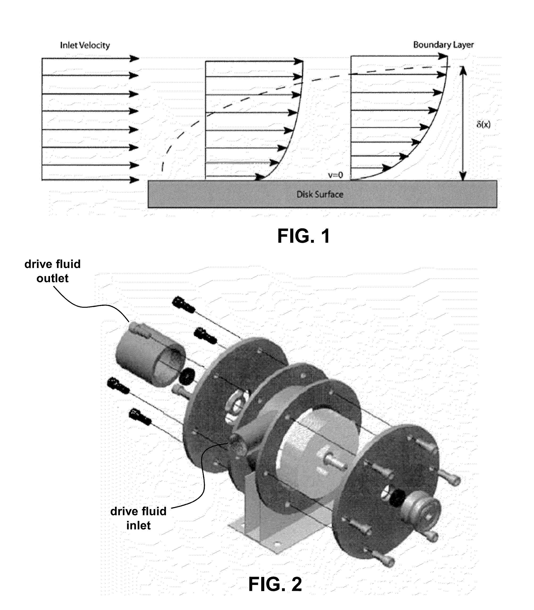
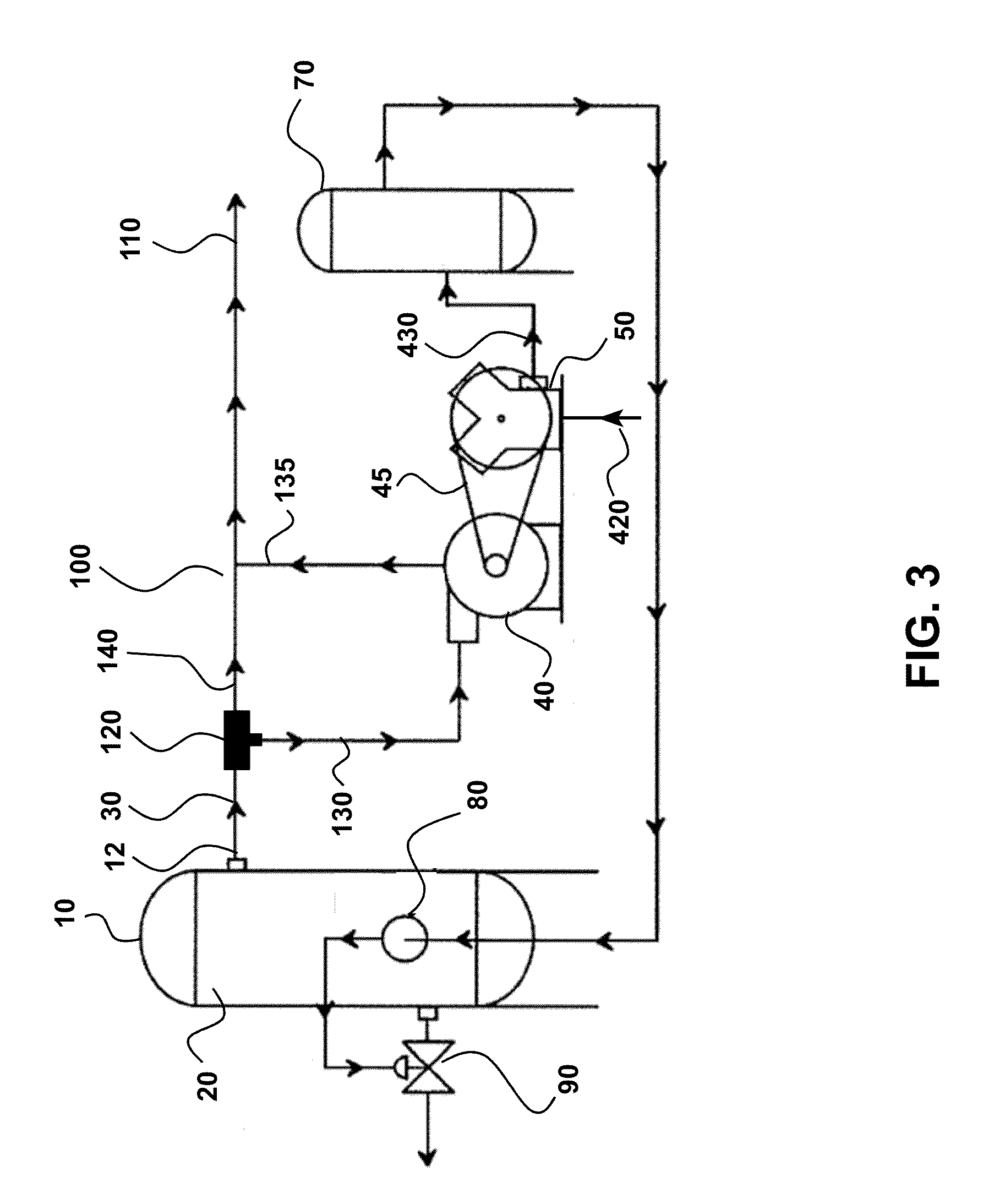
[0073]FIG. 3 summarizes a method and system where the BLDT is used to provide pneumatic control. A pressure vessel 10 contains a source of pressurized drive fluid 20 and controller 12. Pressurized fluid 20 provides a flow of a pressurized drive fluid 30 over a BLDT 40 that is mechanically coupled to a compressor pump 50 by mechanical coupling 45. In this fashion, the pressurized drive fluid 30 flowing over the BLDT 40 mechanically powers compressor pump 50. Compressor pump 50 compresses a compressible fluid 420, such as air. Compressed fluid 430 is directed into a retention tank 70. The compressed fluid can be used to run controls, including a pneumatic device such as a level controller 80 and / or a dump valve 90. The dump valve regulates the amount of liquid removed from pressure vessel 10. In this example, the drive fluid may be a hydrocarbon gas such as a natural gas that is contained in a closed loop 100 and fed to an outlet flow conduit 135 o...

example 2

Self-Powered Compressor

[0076]One important aspect of the industrial processes provided herein is the compressor pump that is powered by fluid flow, wherein the fluid flow is an inherent part of the industrial process and external energy input is not required to generate the flow or power the compressor. This aspect is referred to as a “self-powered compressor” as no external source of energy is required to drive the compressor, but the inherent high pressure of the drive fluid is harnessed to generate mechanically-based compression. As discussed, the action of the compressor can itself be harnessed to provide useful control of various aspects of the industrial process without relying on an external energy source (see, e.g., the process flow summarized FIG. 5). This can significantly reduce the cost of the process by not only minimizing external power consumption, but by avoiding additional components, increasing reliability of the process, and reducing unwanted emissions.

[0077]FIG. ...


PUM


Abstract

Provided are various devices and processes that harness the inherent kinetic energy of a flowing pressurized fluid to drive a compressor to compress a fluid without any need for electrical or chemical energy. The flowing drive fluid flows over a boundary layer disk turbine, or Tesla turbine, which is mechanically coupled to a compressor that compresses a fluid. The flowing fluid may be a natural gas from a hydrocarbon recovery operation. The compressed fluid may be air that is used to power a pneumatic device in an industrial process. Harnessing the kinetic energy of the flowing fluid increases economic efficiency of the process, while also avoiding unwanted emissions adverse to the environment and public health.

Description

CROSS-REFERENCE TO RELATED APPLICATIONS[0001]This application claims the benefit of priority of U.S. Provisional Patent Application No. 61 / 535,176, filed Sep. 15, 2011, which is hereby incorporated by reference in its entirety.BACKGROUND OF THE INVENTION[0002]Provided herein are devices and methods for driving and controlling industrial processes using inherent kinetic energy of a fluid that is an integral part of the industrial process. In this manner, the environmental impact from the industrial process is significantly reduced and revenue to the producer increased, while maintaining and even increasing reliability and efficiency.[0003]Conventional industrial processes may power a pneumatic device by pressurized fluid. For example, typical petroleum industry pneumatic process control devices and instruments are often powered by pressurized natural gas from a supply such as from wellhead production equipment (i.e., a petroleum separator) through a series of valves, regulators, and ...

Claims


Application Information

Patent Timeline
Patent Type & Authority Applications(United States)
IPC IPC(8): F04B47/08
CPCF04B35/01F04D17/161F01D1/36
Inventor BEELER, CASEY L.
Owner LEED FABTION SERVICES
Why Eureka
Try Eureka