Terminal clamp for a moisture sensor for monitoring a vascular access

a moisture sensor and clamping technology, applied in the field of clamping for moisture sensors, can solve the problems of difficult accumulation of dirt, and achieve the effect of reliable electrical contact, cost-effective and in large numbers

Active Publication Date: 2013-03-21
FRESENIUS MEDICAL CARE DEUTSCHLAND GMBH
View PDF9 Cites 31 Cited by
  • Summary
  • Abstract
  • Description
  • Claims
  • Application Information

AI Technical Summary

Benefits of technology

[0008]A problem underlying the present invention is to provide a terminal clamp for a moisture sensor for monitoring a vascular access, which can be produced cost-effectively and in large numbers and also permits reliable electrical contacting even under mechanical loads.
[0017]In a further particularly preferred exemplary embodiment, the lateral stop elements of the guide piece each comprise at the mutually opposite inner sides a bevel with which the terminal tab is centred during the introduction into the terminal clamp. The introduction of the terminal tab is thus facilitated.
[0019]The lower end pieces of the upper and lower legs are preferably in one piece, so that the terminal clamp can be produced favourably in large numbers in the injection moulding process. The one-piece embodiment of the terminal clamp as an injection-moulded part without slots or recesses has the advantage that the hose clamp can be cleaned particularly well. For example, the hose clamp can be disinfected with a dip disinfection procedure. Moreover, it is very difficult for dirt to accumulate because, in contrast with the known clamps, which comprise a plurality of elements, for example upper and lower sections, connection pieces, springs etc., slots or recesses in which dirt could easily accumulate are not present.
[0021]The rear end pieces of the upper and lower legs are preferably constituted as a connection piece with a cross-section which is essentially semicircular when the terminal clamp is opened. A terminal clamp easy to handle, which has relatively small dimensions, is thus created with a relatively straightforward geometry and relatively low mechanical stresses in the components.
[0023]In order to allow the terminal clamp to be gripped in a better fashion when the legs are pressed together, one of the two legs, preferably the lower leg of the terminal clamp, comprises a gripping recess. The gripping recess allows the user to grip the terminal clamp easily and to exert a targeted counterforce during opening or closing of the clamp. This thus prevents the terminal clamp from being pressed on the patient's arm during opening and closing.

Problems solved by technology

Moreover, it is very difficult for dirt to accumulate because, in contrast with the known clamps, which comprise a plurality of elements, for example upper and lower sections, connection pieces, springs etc., slots or recesses in which dirt could easily accumulate are not present.

Method used


Image

  • Terminal clamp for a moisture sensor for monitoring a vascular access
  • Terminal clamp for a moisture sensor for monitoring a vascular access
  • Terminal clamp for a moisture sensor for monitoring a vascular access

Examples


Embodiment Construction

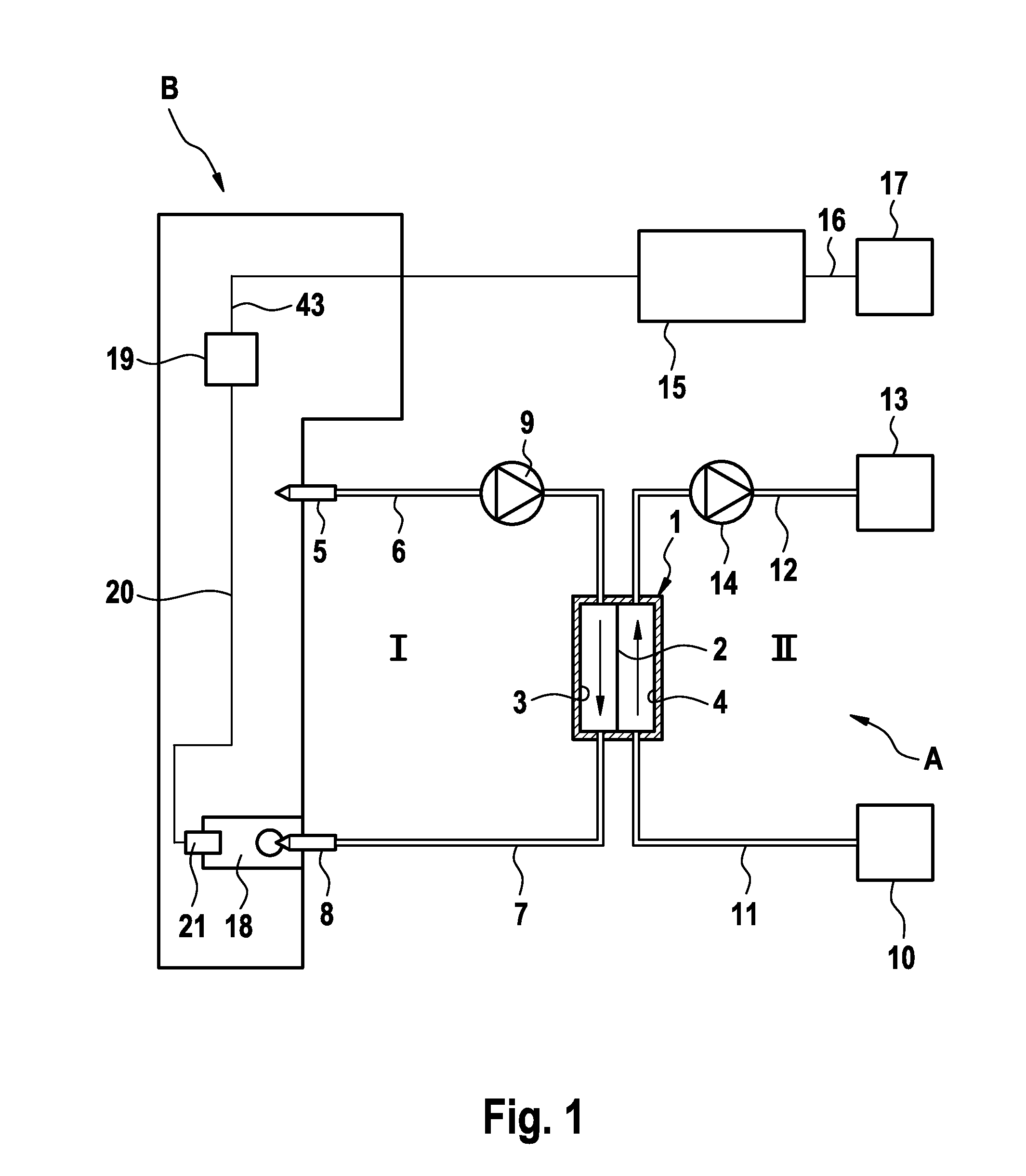
[0038]FIG. 1 shows the main components of an extracorporeal blood treatment apparatus A, in particular a haemodialysis apparatus, which comprises a device B for monitoring the vascular access. In the present exemplary embodiment, monitoring device B is a component of haemodialysis apparatus A.

[0039]Haemodialysis apparatus A comprises a dialyser 1, which is divided by a semipermeable membrane 2 into a blood chamber 3 and a dialysing fluid chamber 4. Connected to the fistula or the shunt of the patient by means of an arterial puncture cannula 5 is an arterial hose line 6, which leads to the inlet of blood chamber 3 of dialyser 1. Leading away from the outlet of blood chamber 3 of dialyser 1 is a venous hose line 7, which is connected by means of a venous puncture cannula 8 to the fistula or the shunt of the patient. A blood pump 9, which conveys the blood in extracorporeal blood circuit I, is incorporated into arterial hose line 6.

[0040]Dialysing fluid circuit II of dialysis apparatus...


PUM


Abstract

A terminal clamp for a moisture sensor to be placed on a patient's skin in order to monitor a vascular access to a patient includes first, lower and second, upper legs for clamped fixing of terminal tab of moisture sensor, rear end pieces of the legs being connected. The terminal clamp includes terminal contacts for contacting electrical contact points of terminal tab, and a guide piece having a slot-shaped cutout for receiving terminal tab. Slot-shaped cutout of guide piece is bounded laterally by two stop elements so that terminal tab is held in terminal clamp in a predetermined position, in which terminal contacts of terminal clamp contact the electrical contact points of terminal tab. Upper leg comprises a latching device, which is fixed in slot-shaped cutout in a snap-in manner when terminal clamp is closed to lock upper leg in position on lower leg.

Description

CROSS REFERENCE TO RELATED APPLICATIONS[0001]The present application claims priority to U.S. Provisional Application Ser. No. 61 / 537,082, filed on Sep. 21, 2011, and claims priority to Application No. DE 10 2011 113 839.4, filed in the Federal Republic of Germany on Sep. 21, 2011, each of which is expressly incorporated herein in its entirety by reference thereto.FIELD OF INVENTION[0002]The present invention relates to a terminal clamp for a moisture sensor to be placed on a patient's skin in order to monitor a vascular access to a patient. Moreover, the present invention relates to an arrangement comprising the moisture sensor and the terminal clamp. Furthermore, the present invention relates to a device for monitoring a vascular access in an extracorporeal blood treatment, wherein a patient's blood is carried away from the patient via an arterial hose line which comprises an arterial cannula and is fed to the patient via a venous hose line which comprises a venous cannula, wherein...

Claims


Application Information

Patent Timeline
Patent Type & Authority Applications(United States)
IPC IPC(8): A61M5/50A61M1/14
CPCA61M1/3653A61M1/367A61M1/3656A61M2205/14A61M2205/13A61M1/3659Y10S439/909A61B5/0537A61B5/0531H01R4/28
Inventor HEPPE, JOHNLIPPERT, SIMONEWUEPPER, ANDREAS
Owner FRESENIUS MEDICAL CARE DEUTSCHLAND GMBH
Why Eureka
Try Eureka