Coil parts and method of fabricating the same

Active Publication Date: 2013-04-04
SAMSUNG ELECTRO MECHANICS CO LTD
View PDF10 Cites 23 Cited by
  • Summary
  • Abstract
  • Description
  • Claims
  • Application Information

AI Technical Summary

Benefits of technology

The invention aims to improve the fabrication process of coil parts by efficiently performing the processes of forming a coil layer with a primary coil and a secondary coil, and adding magnetic layers on both sides of the coil layer. The invention also seeks to improve productivity and reduce fabrication costs by preventing process defects that occur when performing a thin-film process on a ferrite substrate.

Problems solved by technology

When more data are communicated between a main device and a peripheral device over a GHz RF channel, it is difficult to provide smooth data processing due to a signal delay and other noises.
However, conventional EMI prevention parts are used only in limited fields such as large-area substrates because they are coil-type and stack-type and have large chip part sizes and poor electrical characteristics.
Also, in order to perform a thin-film process on the top surface of the first magnetic substrate 1, it should be modified into a wafer shape or a shape capable of processes such as photo and deposition, leading to an inefficiency in the fabrication process.
Also, since the first magnetic substrate 1 for the conventional common-mode filter is a hard ferrite substrate, it may be broken and damaged during the fabrication process.

Method used


Image

  • Coil parts and method of fabricating the same
  • Coil parts and method of fabricating the same
  • Coil parts and method of fabricating the same

Examples


first embodiment

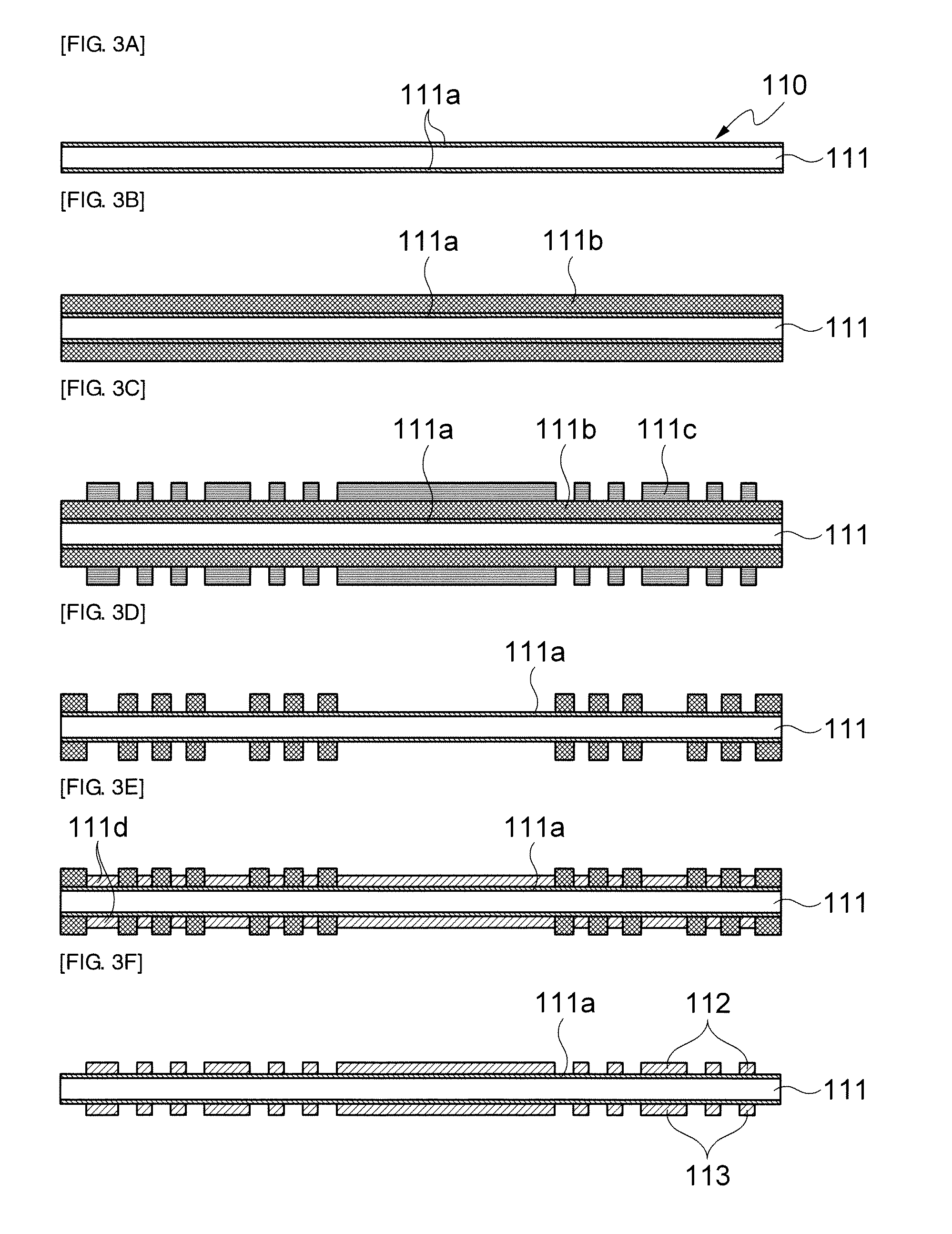
[0056]A coil part and a fabricating method thereof in accordance with the present invention will be described below in detail with reference to FIGS. 2 and 3A to 3G.

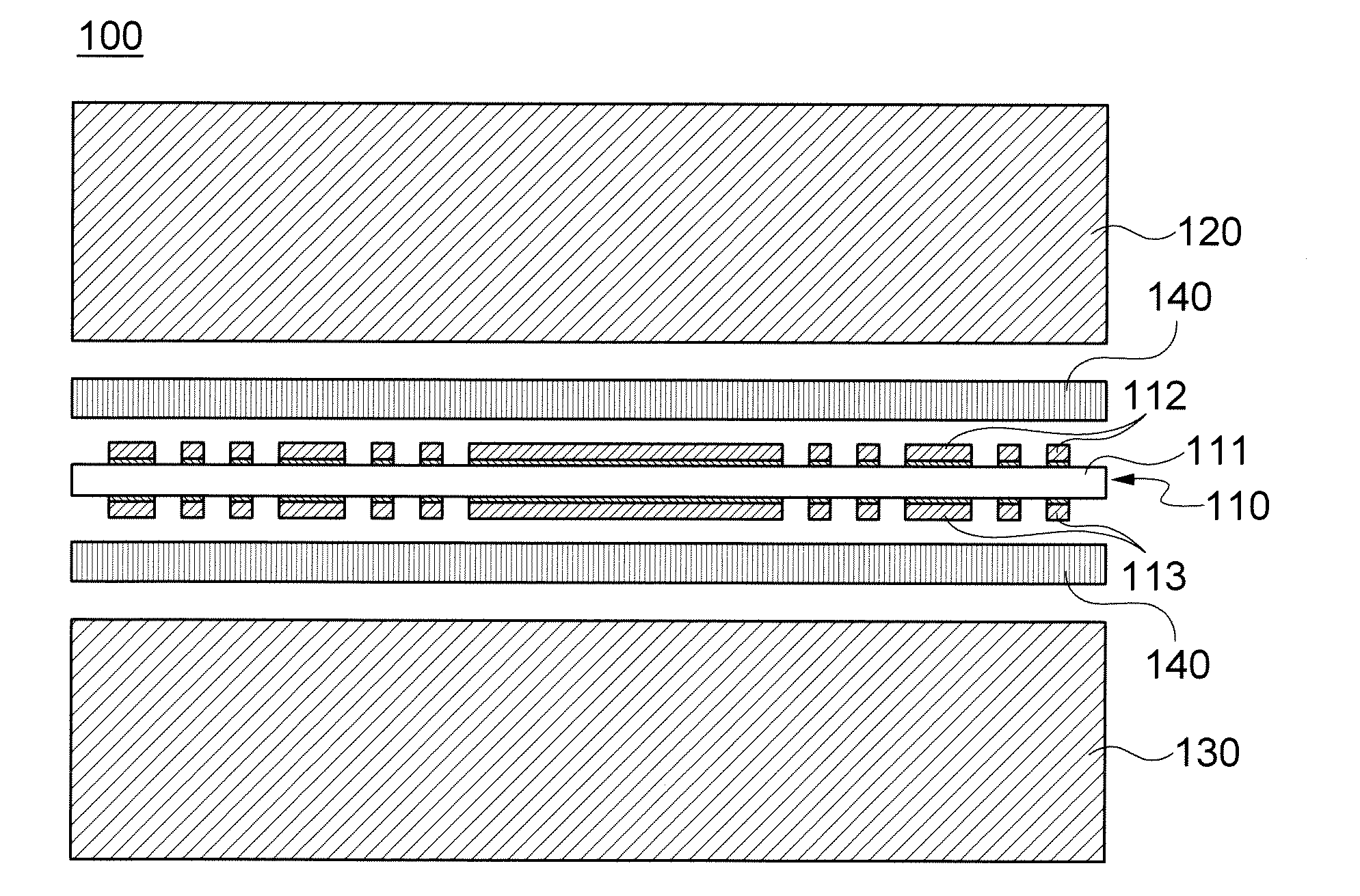
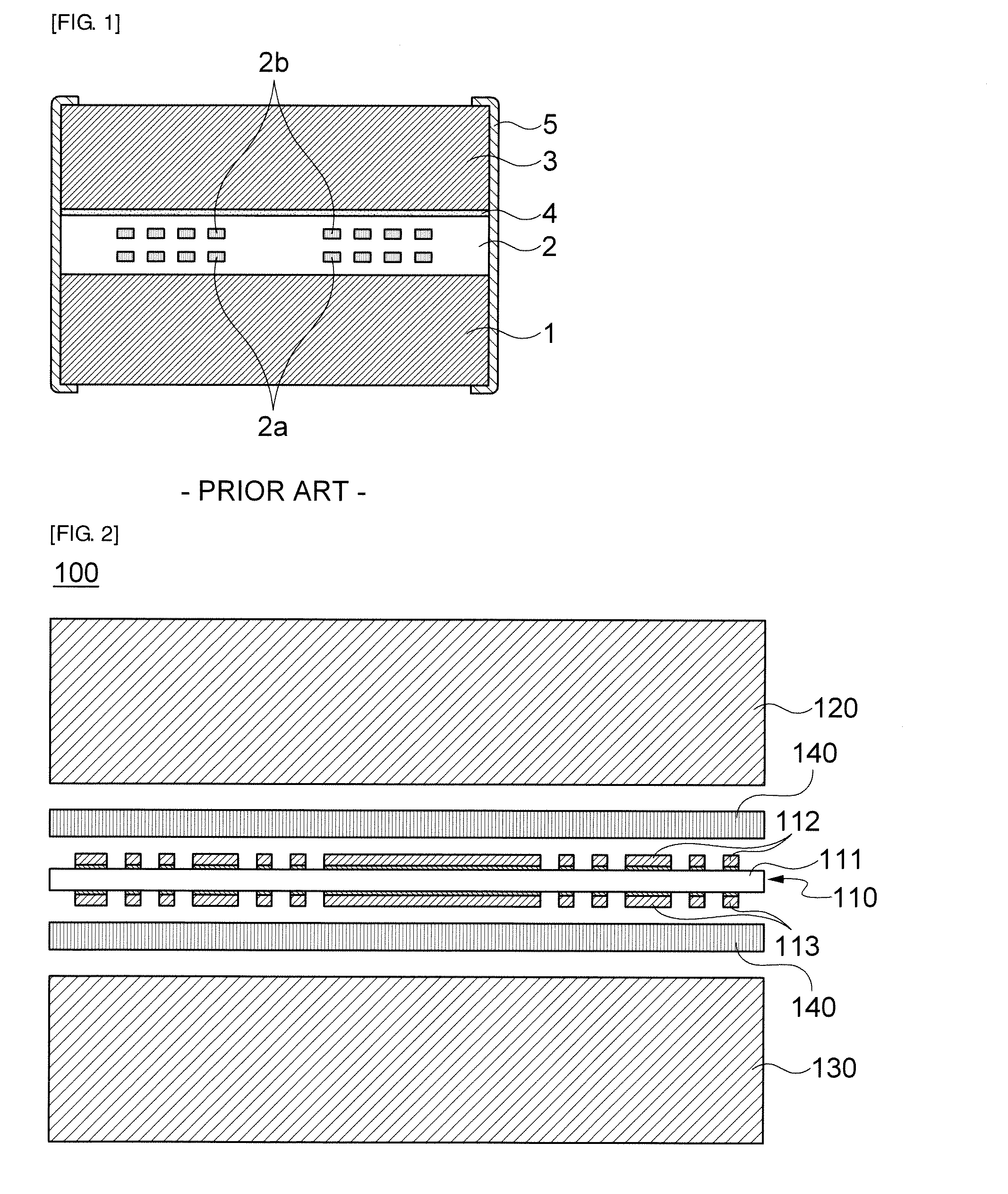
[0057]Referring to FIG. 2, a coil part 100 in accordance with a first embodiment of the present invention includes a coil layer 110, an upper magnetic layer 120 bonded on the coil layer 110, and a lower magnetic layer 130 bonded under the coil layer 120.

[0058]The coil layer 110 may include a core 111 and a first coil 112 and a second coil 113 disposed on and under the core 111.

[0059]Herein, the core 111 may be formed of at least one of a glass epoxy, a Bismaleimide Triazine (BT) resin, and a polyimide, to which the present invention is not limited.

[0060]The first coil 112 and the second coil 113 may be formed in the shape of a coil by patterning metal layers disposed on and under the core 111.

[0061]Herein, the patterning may be performed through a lithography process.

[0062]The first coil 112 and the second coil 113 may b...

second embodiment

[0074]A coil part in accordance with the present invention will be described below in detail with reference to FIG. 4.

[0075]As shown in FIG. 4, a coil part 200 in accordance with this embodiment is different from the coil part 100 of the first embodiment in terms of the structure of an adhesive layer 240.

[0076]Specifically, in this embodiment, an adhesive layer 240, used to bond an upper magnetic layer 220 and a lower magnetic layer 230 to a coil layer 210, may be disposed only in the periphery of the coil layer 210 such that a space is formed between the coil layer 210 and the upper magnetic layer 220 and between the coil layer 210 and the lower magnetic layer 230.

[0077]Thus, the coil layer 210 forms a space around a first coil 212 and a second coil 213 to maintain a dielectric constant of the periphery of the coil layer 210 to be ‘1’, thereby making it possible to improve the filtering characteristics to approach the filtering characteristics of a winding-type coil part.

[0078]Exce...

third embodiment

[0079]A coil part in accordance with the present invention will be described below in detail with reference to FIG. 5.

[0080]As shown in FIG. 5, a coil part 300 in accordance with this embodiment is different from the coil part 200 of the second embodiment in terms of the structure of an upper magnetic layer 320.

[0081]Specifically, the coil part 300 of this embodiment further includes a central magnetic layer 321 extending from an upper magnetic layer 320, among the upper magnetic layer 320 and a lower magnetic layer 330 bonded on and under a coil layer 310.

[0082]That is, the central magnetic layer 321 protrudes from the upper magnetic layer 320 and pierces the center of the coil layer 310. Accordingly, the filtering characteristics of the coil part can be improved because a magnetic material passes through the center of the coil layer 310.

[0083]In another embodiment, the central magnetic layer 321 may protrude from the lower magnetic layer 330.

[0084]Except for the structure of the c...


PUM

PropertyMeasurementUnit
Shapeaaaaaaaaaa
Electrical conductoraaaaaaaaaa
Magnetismaaaaaaaaaa

Abstract

A coil part is provided. The coil part includes a coil layer including a core and a first coil and a second coil disposed on and under the core, a lower magnetic layer bonded under the coil layer, and an upper magnetic layer bonded on the coil layer. Accordingly, it is possible to improve process and productivity and cut fabrication costs by preventing process defects that occur during the fabrication process of a coil part using a ferrite substrate.

Description

CROSS-REFERENCE TO RELATED APPLICATIONS[0001]This application claims the benefit of Korean Patent Application No. 10-2011-0099792 filed with the Korea Intellectual Property Office on Sep. 30, 2011, the disclosure of which is incorporated herein by reference.BACKGROUND OF THE INVENTION[0002]1. Field of the Invention[0003]The present invention relates to coil parts, and more particularly, to coil parts and methods of fabricating the same, which can improve process and productivity and cut fabrication costs by preventing process defects that occur during the fabrication process of a coil part using a ferrite substrate.[0004]2. Description of the Related Art[0005]Electronic products, such as digital TVs, smart phones and notebook computers, have functions for data communication in radio-frequency (RF) bands. Such IT electronic products are expected to be more widely used because they have multifunctional and complex features by connecting not only one device but also USBs and other comm...

Claims


Application Information

Patent Timeline
IPC IPC(8): H01F5/00H01F41/04
CPCH01F5/003Y10T29/49073H01F41/046
Inventor YOO, YOUNG SEUCKKWAK, JEONG BOKKIM, YONG SUKLEE, SANG MOONHUR, KANG HEONWI, SUNG KWON
Owner SAMSUNG ELECTRO MECHANICS CO LTD
Why Eureka
Try Eureka