Membrane electrode assembly and method of making the same

Active Publication Date: 2018-03-01
PROTON ENERGY SYST
View PDF5 Cites 3 Cited by
  • Summary
  • Abstract
  • Description
  • Claims
  • Application Information

AI Technical Summary

Benefits of technology

This patent describes a membrane electrode assembly and its manufacturing method. The assembly includes an ionically conductive membrane, a cured recombination layer and an ionomer layer. The method involves depositing a recombination suspension directly onto the membrane to form a recombination layer, reducing the layer to create a cured layer, and then depositing an ionomer layer on top of the cured layer. The technical effects of this patent is improved performance and reliability of membrane electrode assemblies used in fuel cells and other applications.

Problems solved by technology

One of the major difficulties in the development of such fuel cells lies in the synthesis and supply of dihydrogen (or molecular hydrogen).
Such an electrolysis device comes up against undesirable effects.
This induces problems of purity of the gas produced but also induces problems of security.
This, however, causes an increase in the electrical resistance by making it more difficult for the H+ ions to pass through, and lowers the performance of the systems.
However, the recombination reaction of the catalyst particles is exothermal and induces a loss of energy.
Furthermore, such a solution is not optimized for industrial-scale applications since a part of the molecular hydrogen generated at the cathode is nevertheless lost inside the proton-exchange membrane.
Consequently, a part of the molecular hydrogen nevertheless reaches the anode since the quantity of molecular oxygen is insufficient in the catalyst particles disposed in the membrane.

Method used


Image

  • Membrane electrode assembly and method of making the same
  • Membrane electrode assembly and method of making the same
  • Membrane electrode assembly and method of making the same

Examples


example 1

[0038]In Example 1, a membrane electrode assembly was manufactured including a recombination layer deposited onto a NAFION™ membrane, an ionomer layer deposited on the recombination layer, an anode catalyst layer applied to the ionomer layer, and a cathode catalyst layer applied to the surface of the NAFION™ membrane opposite that of the recombination layer.

[0039]The recombination suspension used included a platinum diamine dinitrate solution containing 6 mg Pt / ml. The ionomer layer included a 5 weight percent solids NAFION dispersion diluted to 2.5 wt % using isopropyl alcohol.

[0040]The membrane electrode assembly was manufactured according to the process parameters listed in Table 2.

TABLE 2AnodeCathodeRecombinationIonomerCatalyst Catalyst ParameterLayerLayerInkInkDensity (mg / mL)65——% Solids——118Temperature (° C.)80808080Spray Coater Height120120120120(mm)Deposition Flow 1.51.51.51.5Rate (mL / min)Spray Coater Travel120120120120Speed (mm / s)Dwell Time (s)30303030Number of Passes202020...

example 2

[0043]In Example 2, a membrane electrode assembly was manufactured including a recombination layer deposited onto a SOLVAY™ membrane, an ionomer layer deposited on the recombination layer, an anode catalyst layer applied to the ionomer layer, and a cathode catalyst layer applied to the surface of the SOLVAY™ membrane opposite that of the recombination layer.

[0044]The recombination suspension is a platinum diamino dinitrate solution that contains 6 mg Pt / mL. The ionomer suspension is a 5 weight percent solids Solvay ionomer dispersion diluted to 2.5 wt % using 1-propanol.

TABLE 3AnodeCathodeRecombinationIonomerCatalyst Catalyst ParameterLayerLayerInkInkDensity (mg / mL)62.5% Solids——115Temperature (° C.)80808080Spray Coater Height120120120120(mm)Deposition Flow 1.51.51.51.5Rate (mL / min)Spray Coater Travel120120120120Speed (mm / s)Dwell Time (s)10101010Number of Passes20202020

[0045]In Example 2, a membrane electrode assembly was developed in the same manner as in Example 1 using a SOLVAY m...

example 3

[0046]In Example 3, a membrane electrode assembly was manufactured including a recombination layer deposited onto a NAFION™ membrane, an ionomer layer deposited on the recombination layer, an anode catalyst layer applied to the ionomer layer, and a cathode catalyst layer applied to the surface of the NAFION™ membrane opposite that of the recombination layer.

[0047]The recombination suspension is a platinum diamino dinitrate solution that contains 6 mg Pt / mL. The ionomer suspension is a five weight percent Nafion dispersion diluted to 2.5 wt % using IPA.

[0048]The membrane electrode assembly was manufactured according to the process parameters listed in Table 4.

TABLE 4AnodeCathodeRecombinationIonomerCatalyst Catalyst ParameterLayerLayerInkInkDensity (mg / mL)65% Solids——118Temperature (° C.)80808080Spray Coater Height120120120120(mm)Deposition Flow 1.51.51.51.5Rate (mL / min)Spray Coater Travel120120120120Speed (mm / s)Dwell Time (s)10101010Number of Passes20202010

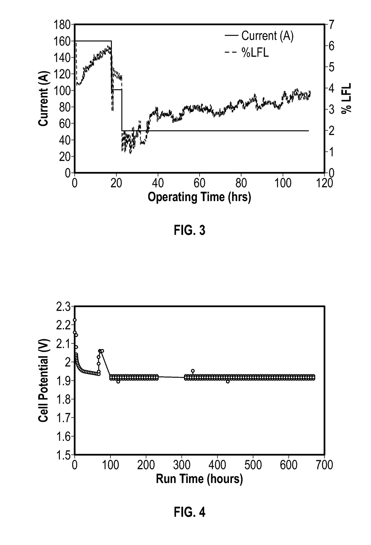
[0049]As shown in FIG. 4, E...


PUM

PropertyMeasurementUnit
Fractionaaaaaaaaaa
Fractionaaaaaaaaaa
Flow rateaaaaaaaaaa

Abstract

Disclosed herein is a method of manufacturing a membrane electrode assembly (MEA) including directly depositing a liquid suspension containing a platinum precursor onto an ionically conductive membrane (e.g., proton-exchange membrane) that, when the platinum precursor deposit layer is reduced, provides a layer that will scavenge hydrogen that has diffused back through the membrane due to cell stack pressure differential.

Description

BACKGROUND[0001]Fuel cells are envisaged as an electric power supply system for future mass-produced motor vehicles as well as for a large number of applications. A fuel cell is an electrochemical device that converts chemical energy directly into electrical energy. Hydrogen (H2) or molecular hydrogen is used as a fuel for the fuel cell. The molecular hydrogen is oxidized on an electrode of the cell and oxygen (O2) or molecular oxygen from the air is reduced on another electrode of the cell. The chemical reaction produces water. The great advantage of the fuel cell is that it averts emissions of atmospheric pollutant compounds at the place where electricity is generated.[0002]One of the major difficulties in the development of such fuel cells lies in the synthesis and supply of dihydrogen (or molecular hydrogen). On earth, hydrogen does not exist in great quantities except in combination with oxygen (in the form of water), sulphur (in the form of hydrogen sulphide) and nitrogen (as ...

Claims


Application Information

Patent Timeline
IPC IPC(8): H01M8/1004H01M8/1027H01M8/1023H01M8/1025H01M8/1041
CPCH01M8/1004H01M8/1027H01M8/1023H01M8/1025H01M8/1055C01G55/004C08F12/16C08F14/18C08G65/226C08G65/4025H01M2008/1095C01G55/001H01M4/881H01M4/8817C25B13/08H01M8/1053H01M8/1039Y02E60/36Y02P70/50Y02E60/50C25B1/04C25B11/00
Inventor CAPUANO, CHRISTOPHER BRYCEPERTOSO, MORGAN ELIZABETHDANILOVIC, NEMANJA
Owner PROTON ENERGY SYST
Why Eureka
Try Eureka