Output Power Limiter in an Audio Amplifier

a technology of output power limiter and audio amplifier, which is applied in the direction of low frequency amplifier, electrical transducer, gain control, etc., can solve the problems of reducing the width of the pwm pulse and reducing so as to reduce the width of the pwm pulse and effectively limit the amount of current that passes through the load

Inactive Publication Date: 2013-04-11
MEYERTONS HOOD KIVLIN KOWERT & GOETZEL P C
View PDF7 Cites 25 Cited by
  • Summary
  • Abstract
  • Description
  • Claims
  • Application Information

AI Technical Summary

Benefits of technology

[0008]Various embodiments of an amplifier feature the capability of limiting output power in the amplifier. The amplifier may include two or more pulse-width modulators (PWM) controlling respective sets of switches, and for large input signals the output load may become susceptible to potential damage. Therefore, it is desirable to attenuate the output of the amplifier in a controlled manner that protects the load without interrupting or compromising the quality of the audio signal in any way. In one set of embodiments, output power in the amplifier may be limited through a pseudo-power limiter, which may be operated to reduce the width of the PWM pulse to the gate of the high-side FET in a push-pull bridge configuration, to effectively limit the amount of current that passes through the load. The output power is defined as the product of the output voltage and output current, P=V*I.

Problems solved by technology

This permits signal processing using digital circuits such as microprocessors and computers, and while analog to digital conversion can be prone to loss, most modern audio systems use the digital approach because digital signal processing techniques are overall more powerful and efficient than signal processing in the analog domain.
The quality and operating precision of these components directly impacts the quality of audio signal processing systems, as designers have to continually overcome numerous difficult design challenges to meet required specifications and quality standards.
The amplifier may include two or more pulse-width modulators (PWM) controlling respective sets of switches, and for large input signals the output load may become susceptible to potential damage.

Method used


Image

  • Output Power Limiter in an Audio Amplifier
  • Output Power Limiter in an Audio Amplifier
  • Output Power Limiter in an Audio Amplifier

Examples


Embodiment Construction

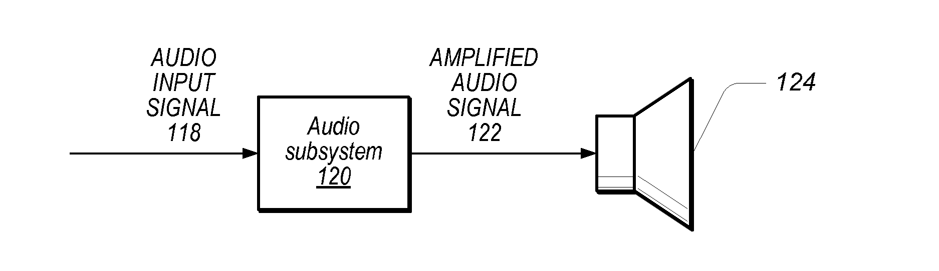
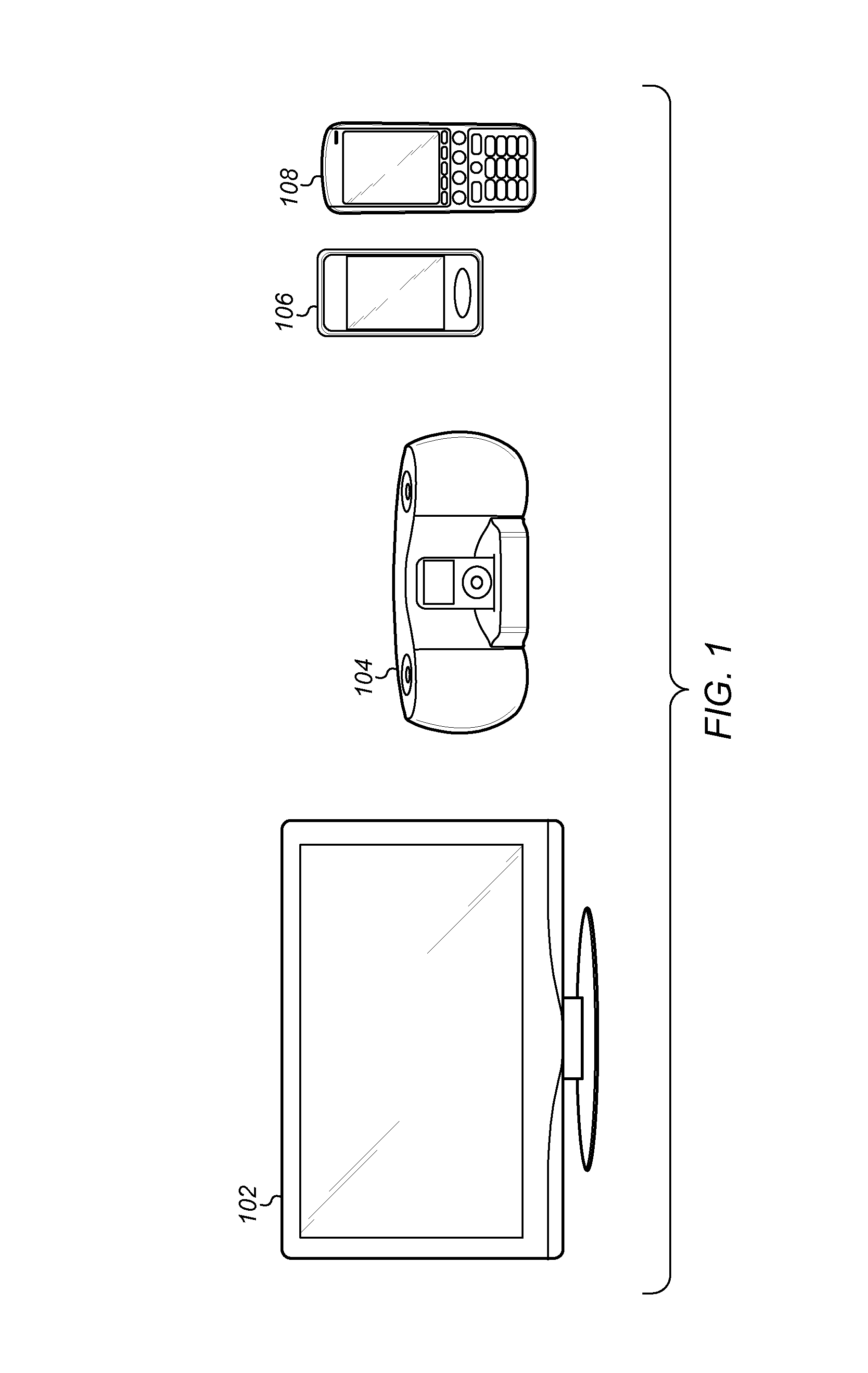
[0028]FIG. 1 illustrates exemplary systems, which may utilize the techniques described above. More specifically, FIG. 1 illustrates exemplary systems, which may utilize an audio subsystem, (which may include an amplifier such as a Class D amplifier), featuring various improvements. As shown, embodiments of the techniques disclosed herein may be used in any one ore more of various systems which involve the amplification of signals. For example, embodiments of the invention may be used in various systems that operate to amplify audio signals for provision to a loudspeaker for audible presentation. As shown, the exemplary systems may include a display device 102; an audio system 104, such as a stereo amplified docking station for a portable music player, CD player, etc.; or a telephone 106 and 108, such as a smart phone, e.g., an iPHONE™ or other similar type of smart phone. It should be noted that FIG. 1 is provided by way of example, and is by no means intended to be exhaustive. Acco...


PUM


Abstract

An output power limiter system (PLS) for audio amplifiers may be designed as a feedback control system for protection of the load and/or quality of the audio experience. The PLS may use comparator to sense the output current, compare it to a specified threshold, and assert a signal when the output current reaches and exceeds the specified threshold. The output signal from the comparator may enable a counter that is clocked with a high frequency clock to begin counting to measure the pulse-width of the comparator output. The output of the counter may be averaged through a fast attack and slow release infinite impulse response (IIR) filter having programmable settings to generate a rate of attenuation or rate of release that adjusts a gain correction in terms of decibels (dB). The output of the IIR filter may then be used for attenuating the output current.

Description

PRIORITY CLAIM[0001]This application claims benefit of priority of U.S. provisional application Ser. No. 61 / 543,998 titled “Circuits and Methods Used in Audio Signal Processing”, filed Oct. 6, 2011, which is hereby incorporated by reference in its entirety as though fully and completely set forth herein.FIELD OF THE INVENTION[0002]The present invention relates generally to signal processing and mixed signal circuits, and more particularly to limiting output power in an audio amplifier.DESCRIPTION OF THE RELATED ART[0003]Signal processing represents a combined application of electrical / computer engineering and mathematical principles, primarily directed to the analysis of and operation on either discrete or continuous time signals. Signals of interest can include sound, images, time-varying measurement values and sensor data, for example biological data such as electrocardiograms, control system signals, telecommunication transmission signals such as radio signals, and many others. S...

Claims


Application Information

Patent Timeline
Patent Type & Authority Applications(United States)
IPC IPC(8): H03F99/00
CPCH03F1/26H03F3/189H03F3/2173H03G3/3026H03F3/45H03G1/04H03K5/003H03F3/185H03F3/45179H03F2200/03
Inventor HEINEMAN, DOUGLAS E.PATE, MICHAEL S.
Owner MEYERTONS HOOD KIVLIN KOWERT & GOETZEL P C
Why Eureka
Try Eureka