Dielectric window for plasma processing apparatus, plasma processing apparatus and method for mounting dielectric window for plasma processing apparatus

a technology of dielectric window and plasma processing apparatus, which is applied in the direction of lighting and heating apparatus, spark plugs, and tube/lamp factory adjustment, etc. it can solve the problems of troublesome replacement of slot antenna plates, inability to meet the requirements of plasma uniformity, and disadvantages of conventional apparatuses in cost, so as to achieve high axial symmetry, high plasma stability, and high axial symmetry

Active Publication Date: 2013-04-18
TOKYO ELECTRON LTD
View PDF9 Cites 221 Cited by
  • Summary
  • Abstract
  • Description
  • Claims
  • Application Information

AI Technical Summary

Benefits of technology

[0028]In accordance with a dielectric window for a plasma processing apparatus of an illustrative embodiment, by providing a ring-shaped first dielectric window recess having the tapered shape, there is formed, on an outer region of the dielectric window in a diametrical direction, a region where a thickness of the dielectric window varies continuously. Accordingly, there can be formed a resonance region where the dielectric window has a thickness suitable for various processing conditions for plasma generation. With this configuration, under various processing conditions, high stability of plasma can be obtained on the outer region in the diametrical direction. Further, by providing second dielectric window recesses, a mode locking can be firmly performed in the inner region of the dielectric window in the diametrical direction. In such a case, even if processing conditions are varied in wide variety, a firmly mode-locked region can be formed in the inner region of the dielectric window in the dia

Problems solved by technology

However, in the configuration of the plasma processing apparatus described in Patent Document 1 and in the configuration of a conventional plasma processing apparatus having a flat dielectric window, the requirement for the wide range of process margin and the requirement for the plasm

Method used


Image

  • Dielectric window for plasma processing apparatus, plasma processing apparatus and method for mounting dielectric window for plasma processing apparatus
  • Dielectric window for plasma processing apparatus, plasma processing apparatus and method for mounting dielectric window for plasma processing apparatus
  • Dielectric window for plasma processing apparatus, plasma processing apparatus and method for mounting dielectric window for plasma processing apparatus

Examples


Embodiment Construction

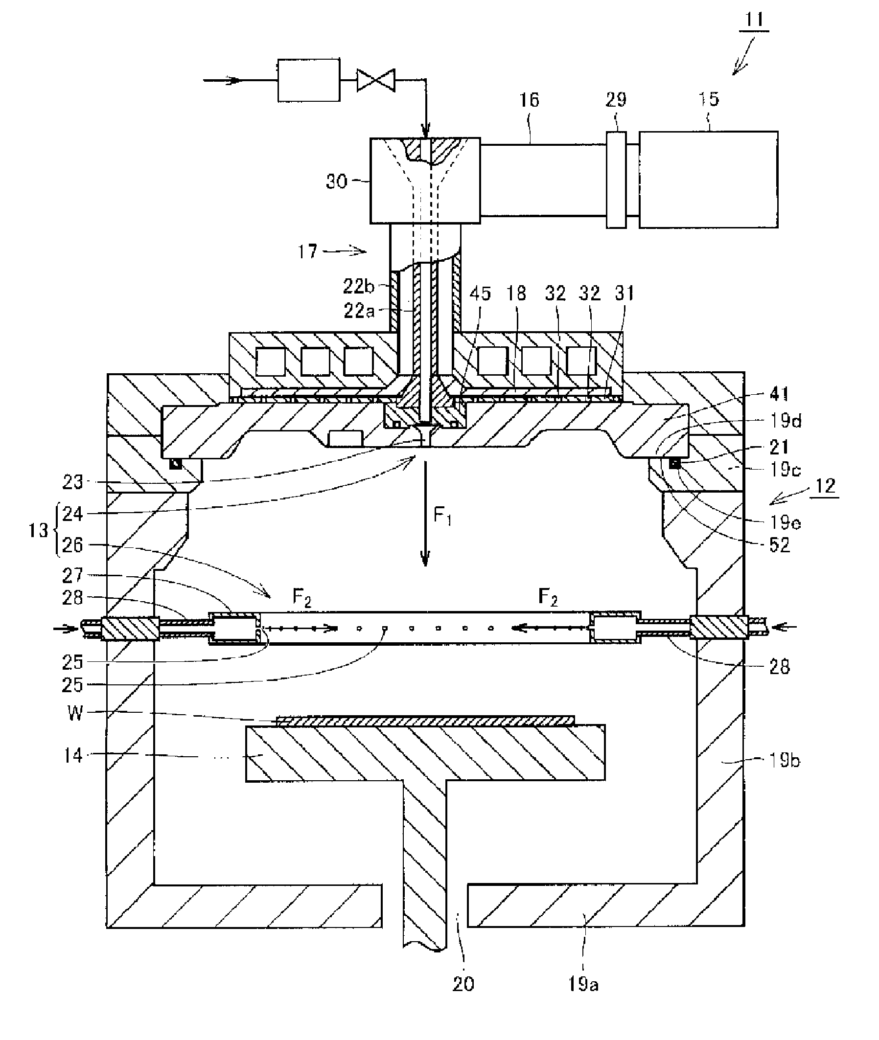
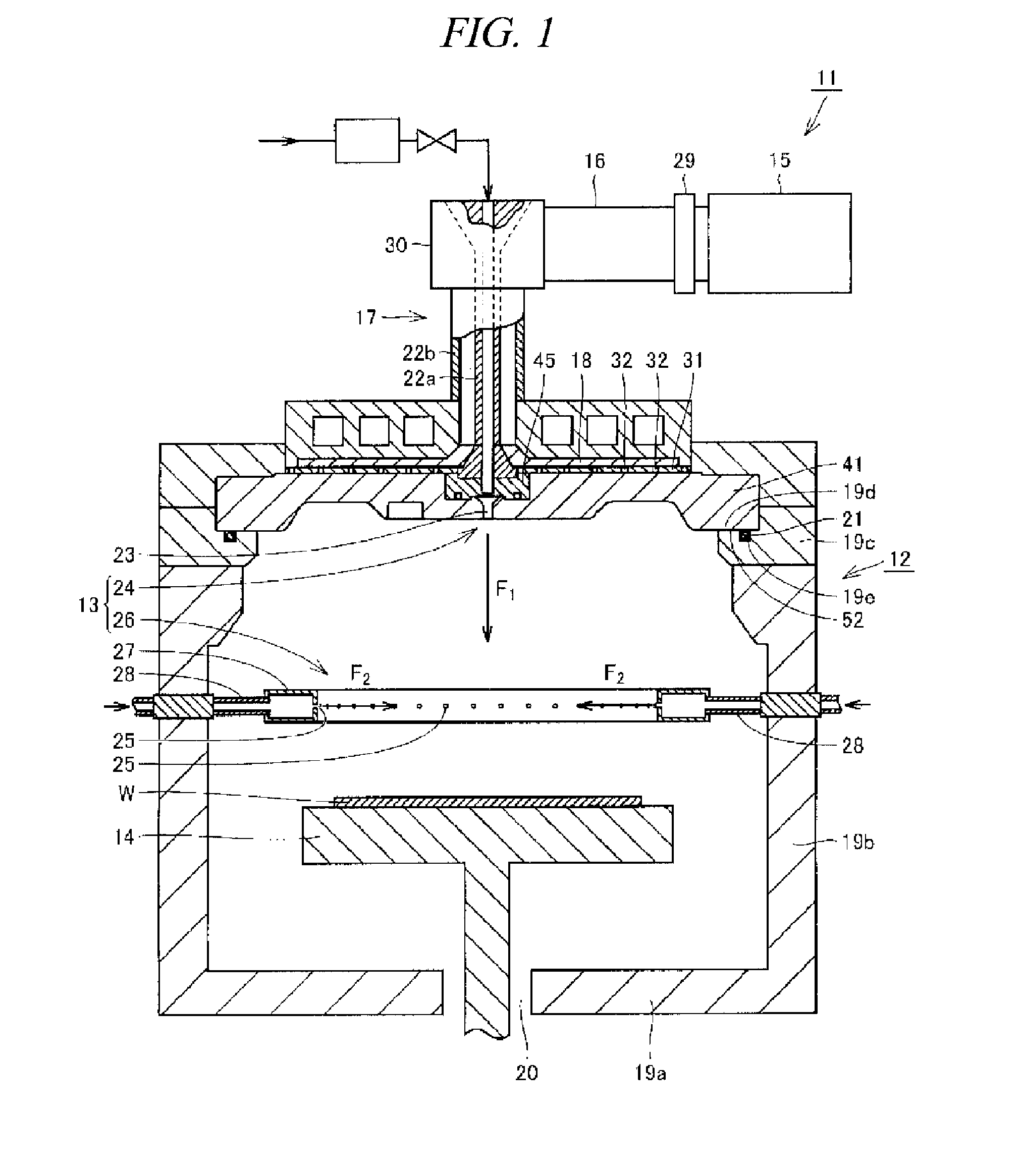
[0057]Hereinafter, illustrative embodiments will be described in detail with reference to the accompanying drawings. First, a configuration of a plasma processing apparatus in accordance with an illustrative embodiment will be explained. FIG. 1 is a cross sectional view schematically illustrating a configuration of a plasma processing apparatus in accordance with an illustrative embodiment. FIG. 2 is a diagram showing a slot antenna plate provided in the plasma processing apparatus shown in FIG. 1, when viewed from a thickness direction of the slot antenna plate.

[0058]Referring to FIGS. 1 and 2, a plasma processing apparatus 11 in accordance with the illustrative embodiment is configured as a microwave plasma processing apparatus that uses microwave as a plasma source. The plasma processing apparatus 11 includes a processing chamber 12, a gas supply unit 13, a holding table 14, a microwave generator 15, a waveguide 16, a coaxial waveguide 17, a dielectric plate 18, a slot antenna pl...


PUM


Abstract

In a dielectric window 41 for a plasma processing apparatus, a first dielectric window recess 47 is formed on an outer region of a surface of the dielectric window 41 in a diametrical direction of the dielectric window 41 at a side where plasma is generated, and the first dielectric window recess 47 is extended in a ring shape and has a tapered shape inwardly in a thickness direction of the dielectric window 41. A multiple number of second dielectric window recesses 53a to 53g are formed between the center of the dielectric window 41 and the first dielectric window recess 47, and each of the second dielectric window recesses 53a to 53g is recessed inwardly in the thickness direction of the dielectric window 41 from the surface of the dielectric window 41.

Description

TECHNICAL FIELD[0001]The present disclosure relates a dielectric window for use in a plasma processing apparatus (hereinafter, simply referred to as a “dielectric window”), a plasma processing apparatus and a method for mounting the dielectric window. Particularly, the present disclosure relates to a dielectric window that transmits microwave and has a substantially circular plate shape. Also, the present disclosure relates to a plasma processing apparatus having the dielectric window and a method for mounting the dielectric window.BACKGROUND ART[0002]A semiconductor device such as an LSI (Large Scale Integrated circuit) or a MOS (Metal Oxide Semiconductor) transistor is manufactured by performing various processes such as etching, CVD (Chemical Vapor Deposition) and sputtering on a semiconductor substrate (wafer) as a processing target substrate. A processing method using plasma as an energy source, i.e., plasma etching, plasma CVD or plasma sputtering may be used to perform the et...

Claims


Application Information

Patent Timeline
IPC IPC(8): H01J23/36H01J9/44
CPCH01J37/32192H01J23/36H01J9/44H01J37/32238H01L21/205H01L21/3065H05H1/46
Inventor YOSHIKAWA, WATARUMATSUMOTO, NAOKIYOSHIKAWA, JUN
Owner TOKYO ELECTRON LTD
Why Eureka
Try Eureka