

System and method for electron spin resonance
a technology of electron spin resonance and system, applied in the field of electron spin resonance, can solve the problems of increasing the effective volume, low q-factor, and lack of convenient variable coupling capabilities to accommodate different types of samples
- Summary
- Abstract
- Description
- Claims
- Application Information
AI Technical Summary
Benefits of technology
Problems solved by technology
Method used
Image

Examples
example 1
[0129]In the present example, a comparative study of several types of resonator systems is described. The study was performed by the inventors of the present invention and published in Review of Scientific Instruments 81, 104703, 2010 as an article entitled “Sensitive surface loop-gap microresonators for electron spin resonance”. The contents of this article are hereby incorporated by reference.
I. INTRODUCTION
[0130]The present inventors recognize that ESR has relative low sensitivity, compared to other spectroscopic techniques (e.g., fluorescence or mass spectroscopy). This is mainly due to the low energy gap between the magnetic-field ESR transitions observed during the ESR experiment. Some conventional ESR spectrometers use induction (Faraday) detection with a high quality (Q-factor) rectangular cavity, which enables a typical sensitivity of about 109 spins / √Hz. Other detection methods include magnetic resonance force microscopy (MRFM), scanning tunneling microscopy combined with ...
example 2
[0171]In the present example, a study of several types of resonator systems according to some embodiments of the present invention is described. The study was performed by the inventors of the present invention and published in Review of Scientific Instruments 82, 076105, 2011 in an article entitled “Note: High sensitivity pulsed electron spin resonance spectroscopy with induction detection”.
[0172]This example presents a surface microresonator that was operated at temperatures ranging from room temperature down to 5K and showed improved measured spin sensitivity, down to 1.5×10⁶ spins / √Hz for a sample of phosphorus doped 28Si (28Si:P). This spin sensitivity corresponds to about 2.5×10⁴ spins for a reasonable one hour of averaging time, which constitutes an improvement of over two orders of magnitude compared to conventional induction detection ESR.
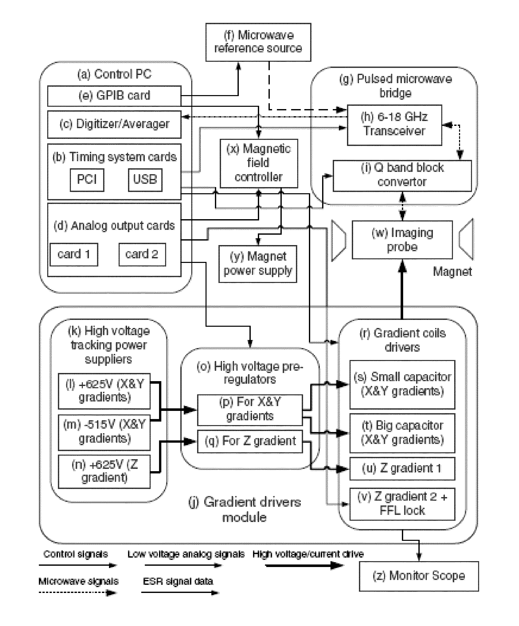
[0173]The pulsed ESR experimental setup is described in details in Blank et al. 2009. Briefly, it is a wide-band, home-made, 6 to 18 GHz ...
example 3
[0185]In this Example, several additional resonator systems which can be utilized according to some embodiments of the present invention are described.
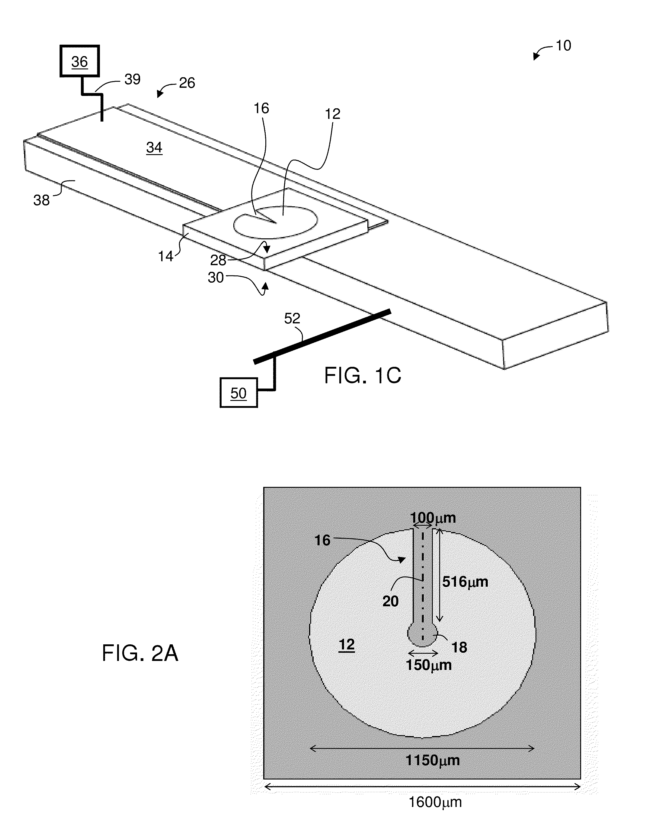
[0186]FIG. 14A shows exemplary dimensions for the disc resonator layer with a Y-shaped gap illustrated in FIG. 2D. The diameter of the disc (see 12 in FIG. 2D) is about 920 μm, and the length of fixed width part (22 in FIG. 2D) is about 280 μm. The length of the widening part (24 in FIG. 2D) is therefore about 920 / 2-280=180 μm. The width of the fixed width part is about 5 μm and the maximal opening of the widening part (at the periphery of the disc) is about 200 μm. The gap as a circular portion (18 in FIG. 2D), 20 μm in diameter, at the center of the disc. The resonator layer is deposited on a 0.22 mm rutile such that the c-axis is parallel to the resonator layer and perpendicular to the longitudinal axis of the gap.
[0187]The room temperature resonance of this resonator layer is about 17.365 GHz with an effective volume of 0.65 mL an...
PUM
 Abstract
Description
Claims
Application Information