
Laser processing system having auxiliary controller

a laser processing system and controller technology, applied in the field of laser processing systems, can solve the problems of laser beam reflected by the surface of the workpiece damage to the mirror, workpiece damage, laser beam reflected by the surface of the workpiece,

Active Publication Date: 2013-05-23
FANUC LTD
View PDF7 Cites 13 Cited by
  • Summary
  • Abstract
  • Description
  • Claims
  • Application Information

AI Technical Summary

Benefits of technology

The invention is a laser processing system that can detect and control the output of a laser using a combination of signals from a numerical control device and an auxiliary controller. This allows for quick detection and response to abnormal processes or the end of a process, increasing production speed. The system also allows for flexible laser control based on the logic signal from the auxiliary controller or by the numerical control device. Additionally, the system can increase laser output based on the amount of light generated from the workpiece during piercing, shortening the time of the laser process.

Problems solved by technology

However, as described above, in the conventional technique, it takes a few milliseconds to ten or longer milliseconds, since the light amount detector detects an abnormality until it is reflected in a laser output, which may result in workpiece being damaged.
Generally, laser cutting cannot be performed on an unprocessed workpiece under cutting process conditions from the beginning.
When the position of the light condensing point in the workpiece is not optimum, the laser beam reflected by the surface of the workpiece damages the mirror in a laser resonator, a fiber for excitation, and the like.
Further, it may damage a mirror of a duct for beam transmission, a lens, and a fiber.
Further, the time required for the piercing process is not constant.
When the piercing process progresses and the hole penetrates the workpiece, light emission weakens.
However, in the conventional method as described above, it takes a few milliseconds to ten or longer milliseconds since a signal from a light amount detector continues to be received until laser irradiation is actually stopped.
The time is unignorable in the case of a laser process in which a process failure occurs when laser irradiation continues and heat input becomes excessive.
Although the problem can be solved by endlessly shortening the interpolation cycle of the numerical control device, the computing power of the numerical control device is limited and the interpolation cycle cannot be shortened if various effective functions are not eliminated.
This is not a realistic solution.
The conventional laser processing system has a problem such that, in digital control by a numerical control device, since it takes too much time for a laser control instruction based on detection of an abnormality by a light amount sensor or detection of completion of a process until stop of a laser output.

Method used


Image

  • Laser processing system having auxiliary controller
  • Laser processing system having auxiliary controller
  • Laser processing system having auxiliary controller

Examples


first embodiment

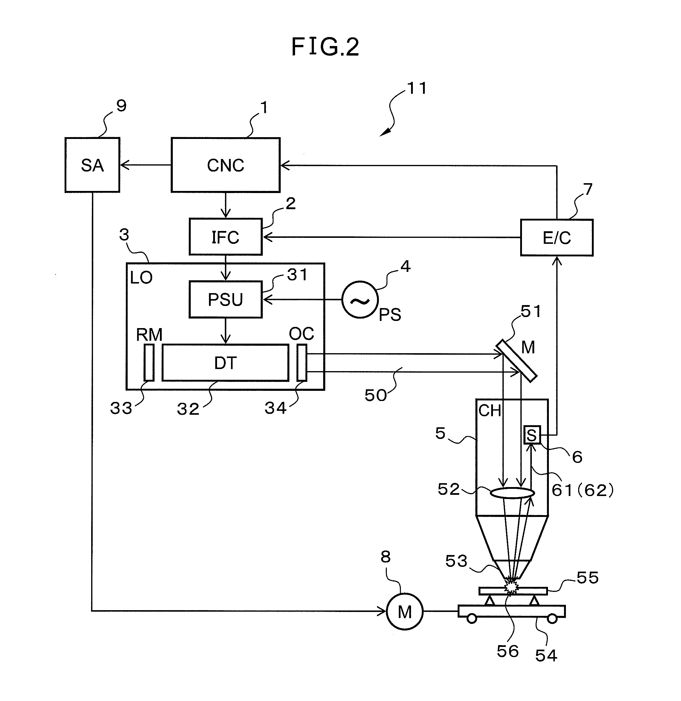
[0036]FIG. 2 is a configuration diagram of a laser processing system according to a first embodiment.

[0037]FIG. 3 shows the configuration of an interface circuit in the laser processing system according to the first embodiment. A laser processing system 11 has a numerical control device 1 outputting a laser output signal for determining a laser output value and a digital signal for determining a transmission period and a stop period of a laser output, a converter 231 converting the laser output signal to an analog signal, an auxiliary controller 7 generating a logic signal that forcedly controls transmission / stop of a laser beam, a pulse signal generator 22 generating a pulse signal for controlling the analog signal on the basis of the digital signal, a logical operation unit 28 performing logical operation using the pulse signal and the logic signal and outputting a result of the logical operation, and a switching device 27 generating a laser drive signal for alternately transmitti...

second embodiment

[0061]A laser processing system according to a second embodiment will now be described. The configuration of the laser processing system according to the second embodiment is similar to that of the laser processing system according to the first embodiment shown in FIG. 2. As shown in FIG. 2, to perform a process by irradiating the workpiece 55 with the laser beam 50, the distance between the process nozzle 53 of the process head 5 and the workpiece 55 has to be optimized. To shorten the tact time, it is important to start irradiation of a laser beam to perform piercing process immediately after the distance between the process nozzle 53 and the workpiece 55 is optimized.

[0062]The laser processing system according to the second embodiment is characterized by a point that a laser power supply unit supplies predetermined excitation energy to a discharge tube, thereby irradiating a workpiece with a distance measurement laser beam for measuring the distance between the process nozzle and...

third embodiment

[0090]A laser processing system according to a third embodiment will now be described. A general configuration of the laser processing system according to the third embodiment is similar to that of the laser processing system according to the first embodiment shown in FIG. 2. FIG. 10 shows the configuration of an interface circuit 200 in the laser processing system according to the third embodiment. The point different from the interface circuits 2 and 20 of the first and second embodiments is that a logical operation unit 29 further comprises a switching circuit 30 for switching use / non-use of the logic signal LS3 output from the auxiliary controller 7.

[0091]The switching circuit 30 can perform the switching by a switching control signal LS1 from the numerical control device 1. For example, as shown in FIG. 10, when the switching circuit 30 switches to a terminal “a”, the logic signal LS4 of the logical operation unit 29 can be set to the low level. When the terminal is switched to...


PUM

PropertyMeasurementUnit
voltageaaaaaaaaaa
temperatureaaaaaaaaaa
distanceaaaaaaaaaa

Abstract

A laser processing system includes: a numerical control device (1) outputting a laser output signal and a digital signal; a converter (231) converting the laser output signal to an analog signal; a pulse signal generator (22) generating a pulse signal for controlling the analog signal; an auxiliary controller (7) generating a logic signal which forcedly controls transmission / stop of a laser beam; a logical operation unit (28, 29) outputting a result of the logical operation between the pulse signal and the logic signal; a switching device (27) generating a laser drive signal for alternately transmitting / stopping the laser output on the basis of the logical operation result; and a sensor (6) for measuring intensity of light radiated or reflected from a workpiece irradiated with a laser beam. The auxiliary controller (7) generates the logic signal in accordance with the intensity of the light measured by the sensor (6).

Description

[0001]This application is a new U.S. patent application and claims benefit of JP 2011-251873, filed on Nov. 17, 2011, the content of JP 2011-251873 is incorporated herein by reference.FIELD OF THE INVENTION[0002]The present invention relates to a laser processing system and, more specifically, to a laser processing system having an auxiliary controller for controlling output of a laser at high speed.BACKGROUND OF THE INVENTION[0003]Laser processing systems in recent years are controlled by a numerical control device performing CNC (computer numeric control), and various functions can be realized by digital control of software. In these laser processing systems, a laser beam is obtained by discharge-exciting a laser medium by a laser power supply device or irradiating a laser medium with excitation light from an excitation light source. The laser beam is condensed to a small region on a workpiece by a condenser lens or the like to conduct a laser process.[0004]In such a system, a dig...

Claims


Application Information

Patent Timeline
Patent Type & Authority Applications(United States)
IPC IPC(8): B23K26/02H01S3/00B23K26/00
CPCB23K26/00B23K26/0626B23K26/42B23K26/03B23K26/70
Inventor MORI, ATSUSHI
Owner FANUC LTD
Learn More