Silicon refining equipment

a technology of refining equipment and silicon, which is applied in the direction of glass shaping apparatus, lighting and heating apparatus, furnace types, etc., can solve the problems of increased heating, increased production cost, and increased production cost, so as to improve installation security and eliminate impurities

Inactive Publication Date: 2013-05-30
COMMISSARIAT A LENERGIE ATOMIQUE ET AUX ENERGIES ALTERNATIVES
View PDF7 Cites 2 Cited by
  • Summary
  • Abstract
  • Description
  • Claims
  • Application Information

AI Technical Summary

Benefits of technology

[0012]The present invention also aims at providing a solution compatible with the use of a plasma torch directed towards the surface of the melt to eliminate impurities.
[0013]The present invention also aims at improving the security of the installation in case of an incidental or voluntary cooling of the silicon melt causing its solidification.

Problems solved by technology

A disadvantage of this technique is that the silicon already heated by the electromagnetic excitation of the coil surrounding the hot crucible is submitted to an additional heating due to the plasma.
The melting of the walls creates a risk as to the security of the installation, due to the possible liquid metal leakage.
This however discards the inductive excitation winding used to heat the silicon, which poses efficiency problems.
Another disadvantage of hot crucibles, which are generally solid for tightness reasons, is that in case of an incidental solidification of the melted silicon inside of the crucible, the silicon expansion linked to the cooling breaks the crucible, which then cannot be repaired.
This disadvantage is particularly disturbing in industrial applications.
Accordingly, even if the winding itself is cooled (for example, by the flowing of water inside of the spirals), this is not sufficient to cool down the external crucible wall, especially due to the interval between the different turns across the height thereof.
However, a disadvantage of such a refining installation is that the manufacturing of a cold sectorized crucible is particularly difficult and expensive.

Method used


Image

  • Silicon refining equipment
  • Silicon refining equipment

Examples


Embodiment Construction

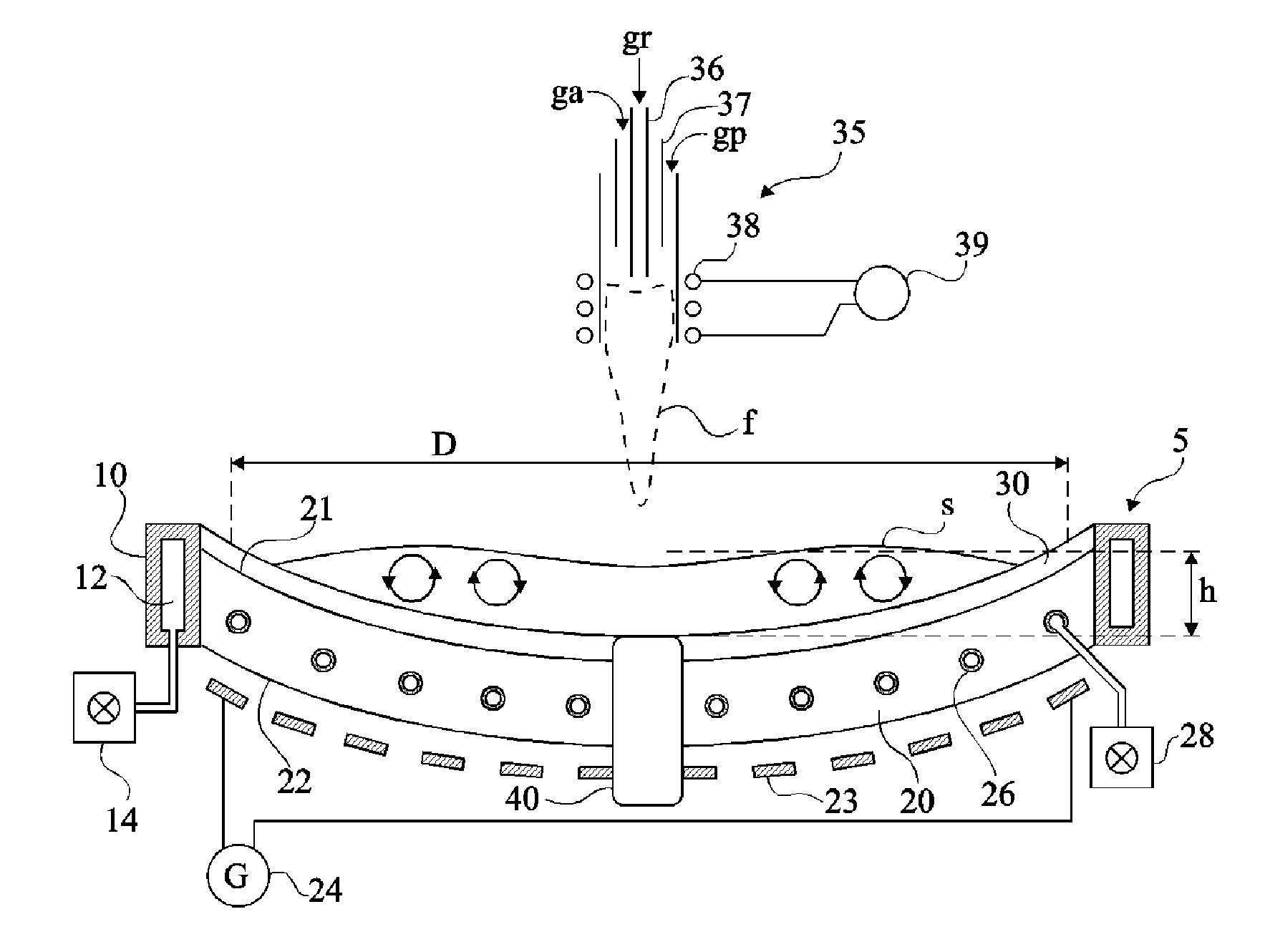
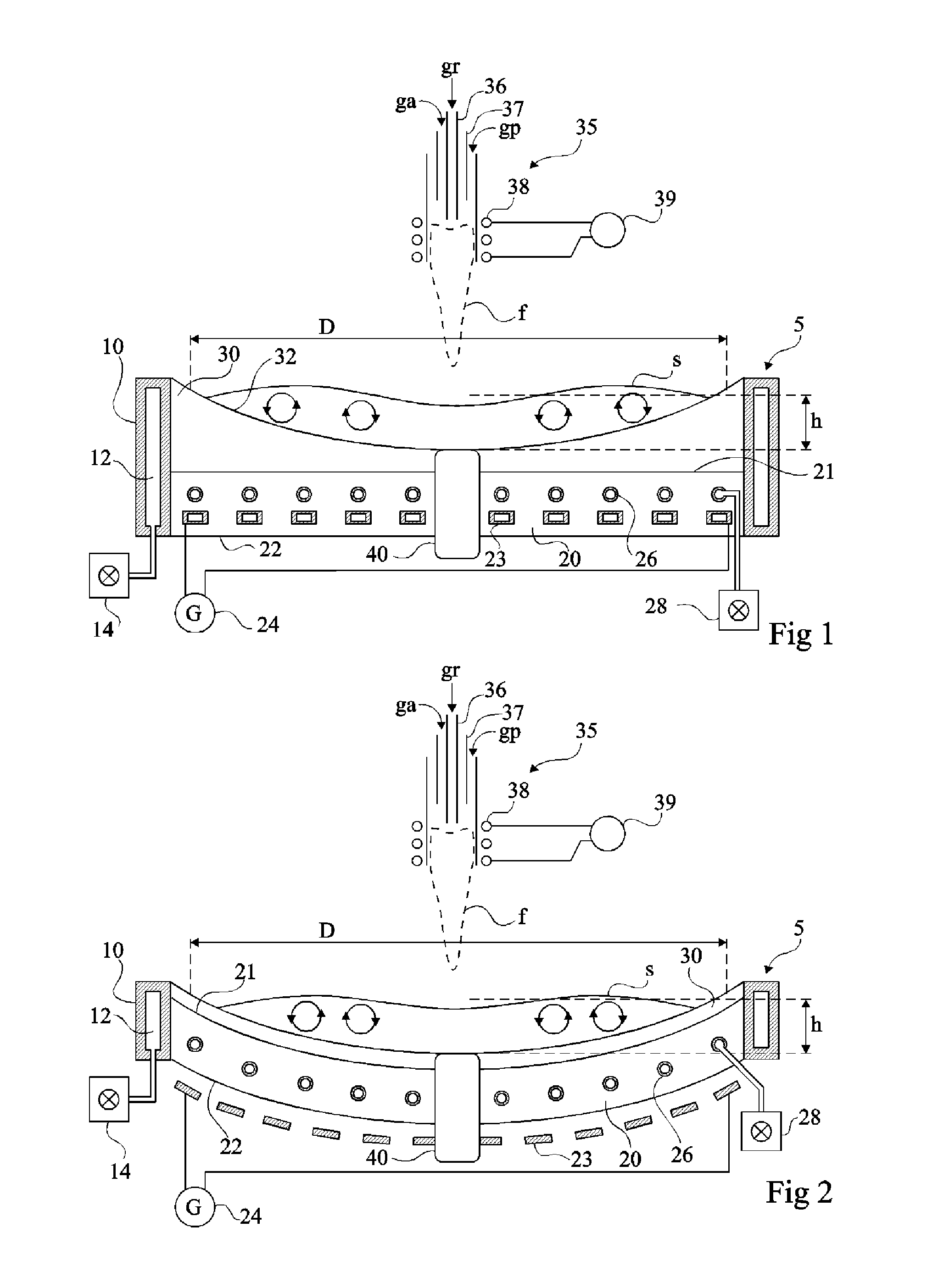
[0028]For clarity, the same elements have been designated with the same reference numerals in the different drawings. Only those components which are useful to the understanding the invention have been shown in the drawings and will be described hereafter. In particular, the constitutive details as well as the gases used in the plasma torch have not been detailed, the present invention being compatible with conventional plasma torch refining methods. Further, the frequencies and intensities of excitation of the inductive windings have not been detailed, the invention being here again compatible with usual techniques of determination of these frequencies and intensities.

[0029]A feature of the present invention is to provide a crucible comprising a cooled-down sole, also called bottom or floor, made of a refractory material and to provide inductive means for heating the silicon melt comprising a coil which is arranged in the sole or under the sole. The cooled-down lateral wall of the ...


PUM

PropertyMeasurementUnit
melting temperatureaaaaaaaaaa
thicknessaaaaaaaaaa
thicknessaaaaaaaaaa

Abstract

The invention relates to equipment for refining a load of silicon(s) that comprises a crucible (5) including at least one sole (20) made of a first refractory material having good heat conductivity, means (26, 28) for cooling the sole, a protection member (30) made of at least a second refractory material having low heat conductivity and to be provided between the crucible and the load, and induction heating means (23, 24) of the load including a winding (23) provided in or under the sole.

Description

FIELD OF THE INVENTION[0001]The present invention relates to the manufacturing of silicon to form cells of electric power generation by photovoltaic effect. This silicon of higher grade than metallurgical silicon is generally designated as solar grade or SoG silicon.DISCUSSION OF PRIOR ART[0002]Currently, the silicon intended for photovoltaic techniques is essentially formed of scrap of the microelectronics industry, since the silicon used for photovoltaic applications can contain a proportion of impurities (on the order of one part per million) which is less critical than the impurity level (on the order of one part per billion) generally required in microelectronics.[0003]As a second silicon source for producing silicon adapted to photovoltaic products, it has already been provided to refine the silicon manufactured for metallurgical applications. The silicon used in metallurgy basically contains several percents of impurities such as iron, titanium, boron, phosphorus, etc. which ...

Claims


Application Information

Patent Timeline
Patent Type & Authority Applications(United States)
IPC IPC(8): C03B5/225C03B5/02
CPCC01B33/037F27B14/06F27B14/10Y02E10/547C03B5/021C03B5/225H01L31/1804Y02P70/50
Inventor LAFON, CHRISTOPHEBOEN, ROGERBRUGUIERE, LIONELGIROLD, CHRISTOPHELEMORT, FLORENTBONNETIER, ARMANDRIVAT, PASCALDEL GOBBO, JEAN-PIERREDELAGE, DANIEL
Owner COMMISSARIAT A LENERGIE ATOMIQUE ET AUX ENERGIES ALTERNATIVES
Why Eureka
Try Eureka