Stent devices for support, controlled drug delivery and pain management after vaginal surgery

US20130138134A1Inactive Publication Date: 2013-05-30ELMAN NOEL M +1

Image

  • Stent devices for support, controlled drug delivery and pain management after vaginal surgery
  • Stent devices for support, controlled drug delivery and pain management after vaginal surgery
  • Stent devices for support, controlled drug delivery and pain management after vaginal surgery

Examples


Embodiment Construction

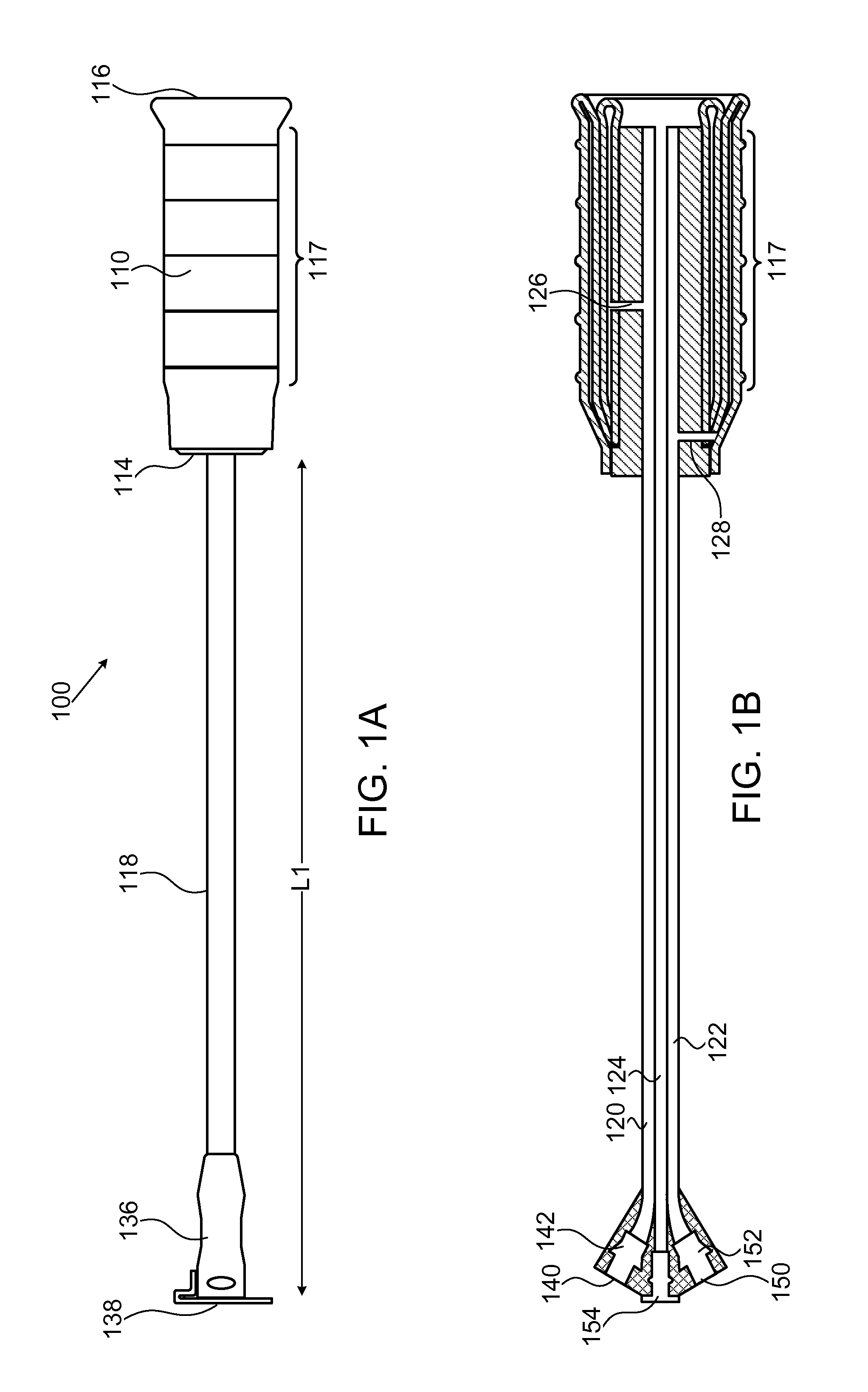
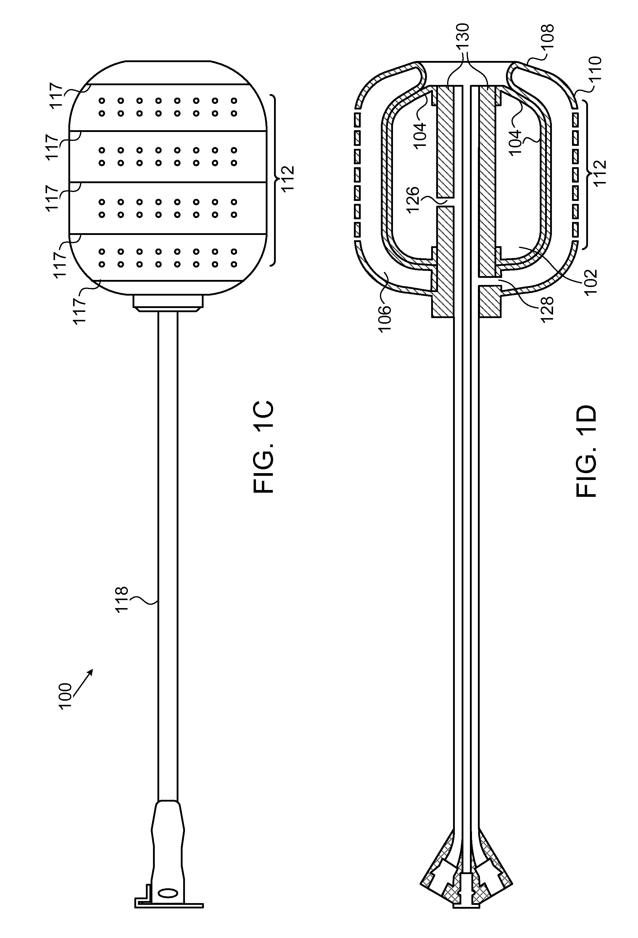
[0036]FIGS. 1A-1F show, in various views, a device 100 according to one embodiment of the invention. FIG. 1A shows an external view of device 100 in a collapsed state. FIG. 1B shows a longitudinal cross section view of device 100 in the same collapsed state. FIG. 1C shows an external view of device 100 in an inflated state. FIG. 1D shows a longitudinal cross section view of device 100 in the same inflated state. FIGS. 1E and 1F show isomeric views of, respectively, the devices in FIGS. 1A and 1C.

[0037]Device 100 includes an inner balloon 102 with an envelope 104, surrounded by an outer balloon 106 which has an internal wall 108 and an external wall 110. This structure is referred to henceforth as a “two-balloon, three-wall” structure. In some embodiments, the inner balloon serves as an inflation or “compression” balloon, while the outer balloon serves as a drug reservoir and is inflatable and capable of controlled drug delivery to surrounding tissue. Outer balloon 106 is hermeticall...


PUM


Abstract

Stent devices comprising an inflatable inner balloon defined by an envelope and an outer balloon surrounding the inner balloon concentrically, the outer balloon serving as a therapeutic agent reservoir used for controlled therapeutic agent delivery. In some embodiments, the outer balloon has two separate walls which define its volume and is independently inflatable. In some embodiments, the two concentric balloons form a substantially cylindrical structure which has a proximal end and a distal end. A catheter carrying inflation and drainage lumens extends outward from the proximal end. In some embodiments, the distal end includes an embedded cervix accommodating tip or has a non-embedded cervix accommodating tip attached thereto. The stent devices can be used to maintain the integrity and placement of vaginally placed mesh or graft after reconstructive procedures, prevent vaginal hematoma formation and bleeding, provide pain control after surgery and deliver antibiotics or hormones to the vaginal epithelium.

Description

CROSS REFERENCE TO RELATED APPLICATIONS[0001]This application claims priority from U.S. Provisional Patent Application No. 61 / 334,176 filed May 13, 2010 and titled “Device to provide mechanical stability post vaginal surgery, and provide controlled drug delivery, including pain management”, which is incorporated herein by reference in its entirety.FIELD AND BACKGROUND[0002]Embodiments of the invention relate in general to post surgery medical devices and more particularly to inflatable devices that provide support, controlled drug delivery and pain management after vaginal surgery.[0003]Gynecological surgery is one of most common types of surgery performed in the USA. Female pelvic medicine and reconstructive surgery is a fairly new field, developed for the treatment of female pelvic disorders which include pelvic organ prolapse, urinary incontinence, chronic and acute pelvic pain, defecatory dysfunction and neurologic disorders of the genitourinary system. In the past five years, p...

Claims


Application Information

Patent Timeline
30 May 2013
Publication
US20130138134A1
IPC
A61M29/02; A61F2/958
CPC
A61M25/0026; A61M25/0068; A61M25/0069; A61M25/008; A61M29/02; A61M31/00; A61M2025/1013; A61M2025/105
Inventors
ELMAN, NOEL M.; APOSTOLIS, COSTAS A.