Tunable inductor circuit

a technology of inductor circuit and inductor, which is applied in the field of communication systems, can solve the problems of increasing the complexity of electronic devices, and achieve the effect of improving the complexity of electronic devices

Inactive Publication Date: 2013-06-06
QUALCOMM INC
View PDF8 Cites 28 Cited by
  • Summary
  • Abstract
  • Description
  • Claims
  • Application Information

AI Technical Summary

Problems solved by technology

The complexity of electronic devices has increased dramatically in the last few years.

Method used


Image

  • Tunable inductor circuit
  • Tunable inductor circuit
  • Tunable inductor circuit

Examples


Embodiment Construction

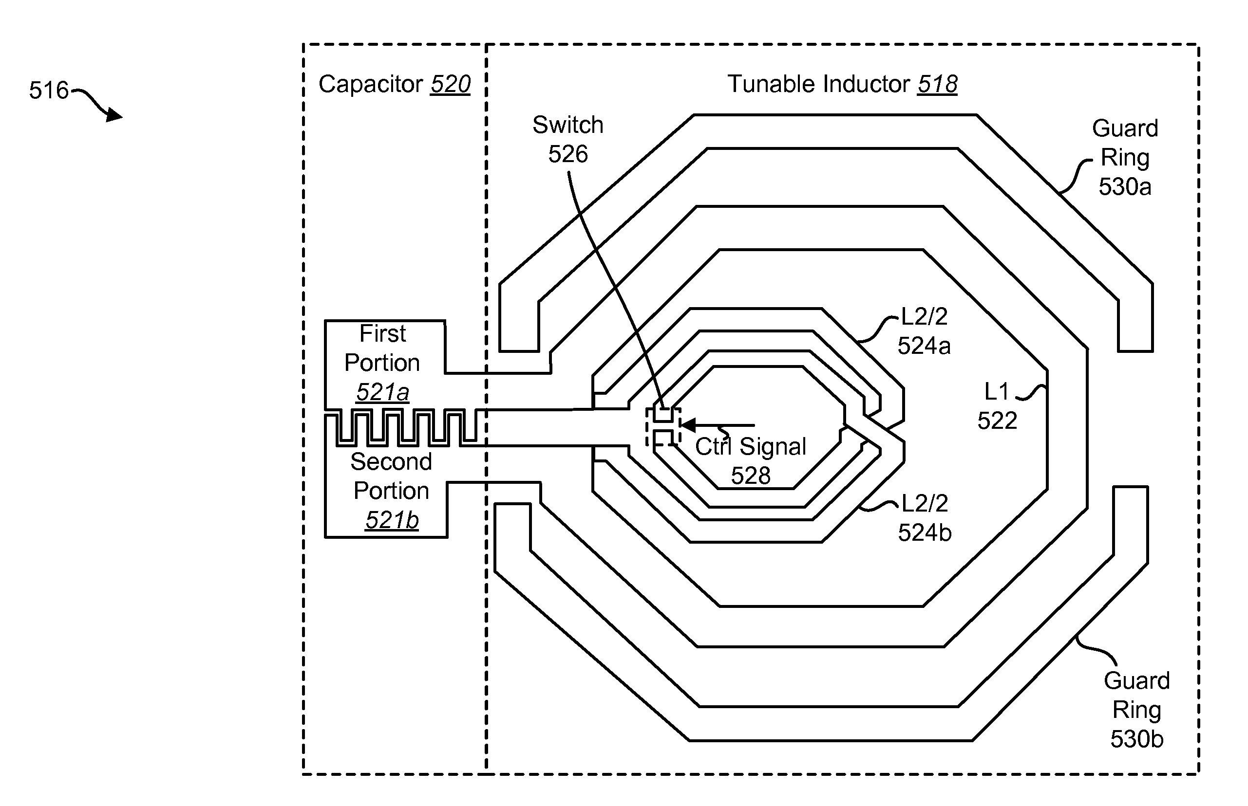
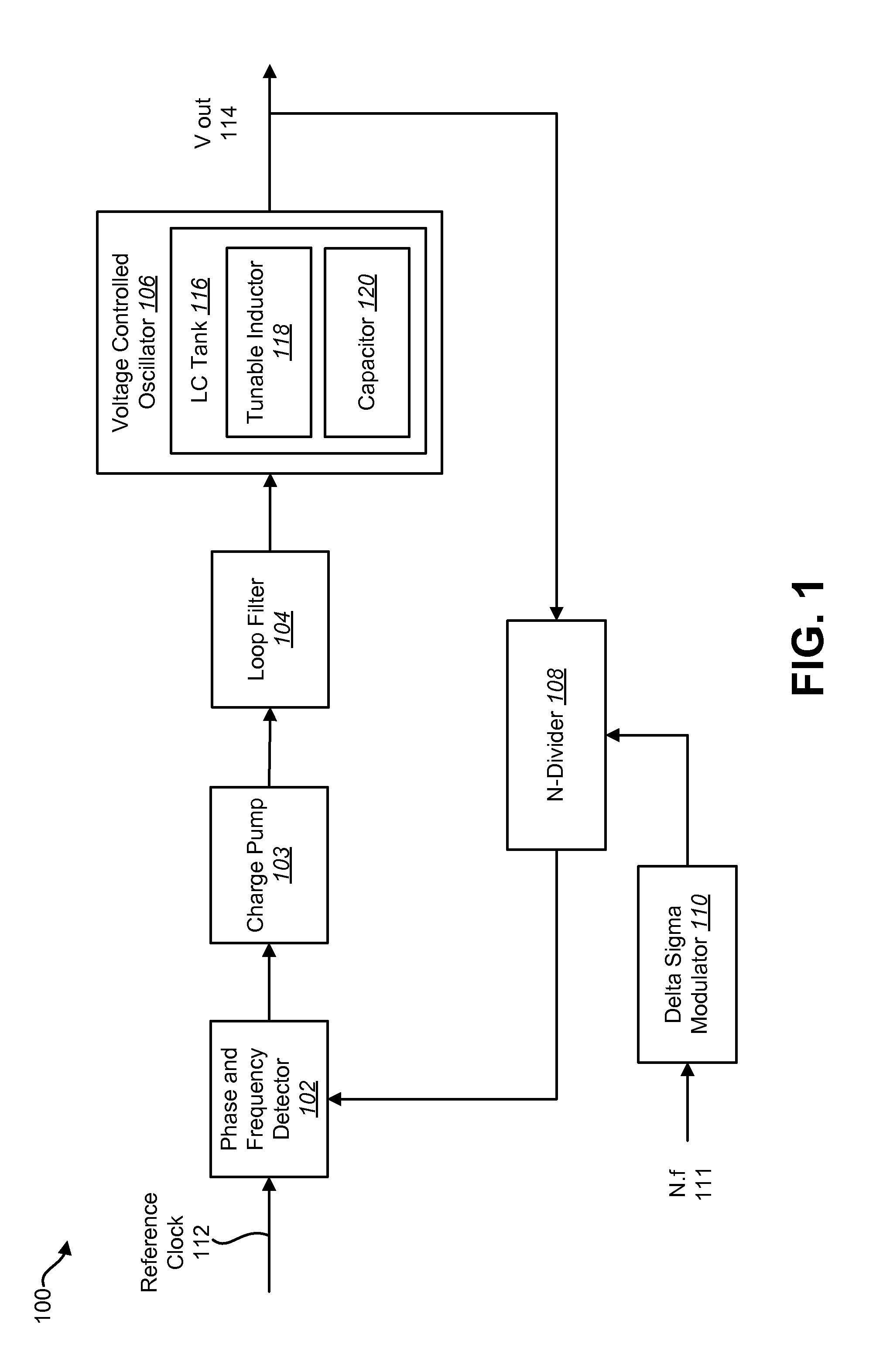
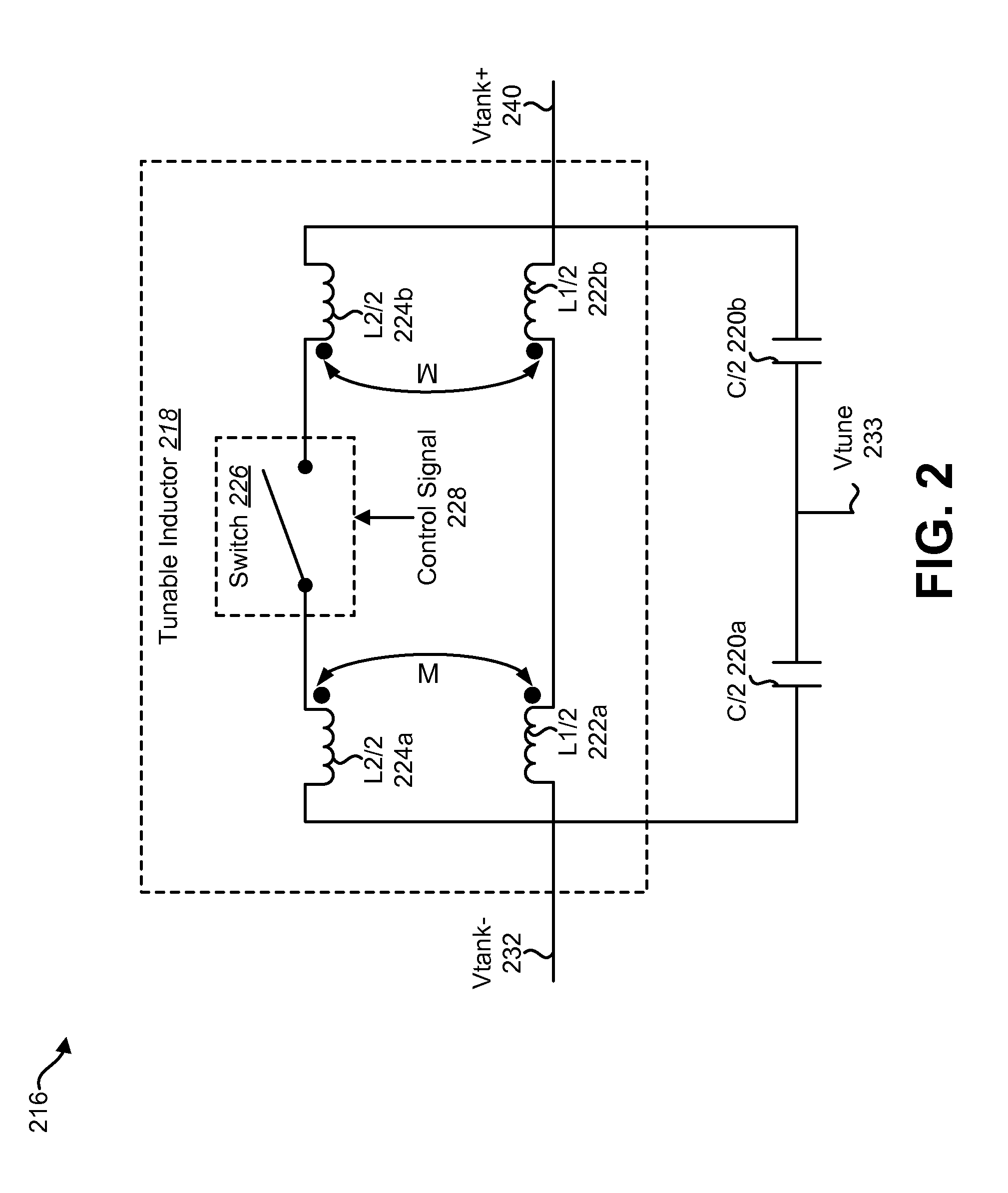
[0023]A phase locked loop (PLL) may be used to generate oscillating signals that are locked, relative to an input reference clock, in phase, frequency or both. This may include using a voltage controlled oscillator (VCO) (or a digitally controlled oscillator (DCO)) to produce an output signal with a frequency based on a VCO input signal. Some VCO designs may use a relatively large tuning range that is difficult to achieve by a single inductor. Therefore, the present systems and methods may use multiple inductors to achieve a relatively large tuning range. Specifically, a tunable inductor may include a first inductor in parallel with a second inductor that is switched. The second, switched inductor may be configured so that the switch resistance is in parallel with the first inductor when the switch is turned on, thus maintaining the quality factor (Q) of the tunable inductor while still achieving a relatively large tuning range. Therefore, the tunable inductor of the present systems...


PUM

PropertyMeasurementUnit
resistanceaaaaaaaaaa
capacitancesaaaaaaaaaa
inductanceaaaaaaaaaa

Abstract

A tunable inductor circuit is disclosed. The tunable inductor circuit includes a first inductor. The tunable inductor circuit also includes a second inductor in parallel with the first inductor. The tunable inductor circuit also includes a switch coupled to the second inductor. A resistance of the switch is added in parallel to the first inductor based on operation of the switch.

Description

TECHNICAL FIELD[0001]The present disclosure relates generally to communication systems. More specifically, the present disclosure relates to a tunable inductor circuit.BACKGROUND[0002]Electronic devices (cellular telephones, wireless modems, computers, digital music players, Global Positioning System units, Personal Digital Assistants, gaming devices, etc.) have become a part of everyday life. Small computing devices are now placed in everything from automobiles to housing locks. The complexity of electronic devices has increased dramatically in the last few years. For example, many electronic devices have one or more processors that help control the device, as well as a number of digital circuits to support the processor and other parts of the device.[0003]Wireless communication systems are widely deployed to provide various types of communication content such as voice, video, data and so on. These systems may be multiple-access systems capable of supporting simultaneous communicat...

Claims


Application Information

Patent Timeline
Patent Type & Authority Applications(United States)
IPC IPC(8): H03B5/12H01F41/00H01F21/00
CPCH01F21/12H01F2021/125H01F27/2804Y10T29/4902H03B5/1268H03B2200/0034H03B2201/0266H03B5/1228
Inventor NARATHONG, CHIEWCHARNJIN, ZHANGLIU, LI
Owner QUALCOMM INC
Why Eureka
Try Eureka