Optimization and control of beam quality for material processing

a laser beam and beam quality technology, applied in the direction of optical elements, manufacturing tools, instruments, etc., can solve the problems of reducing the beam quality, the focal spot size, and the beam divergence, so as to improve enhance the beam quality property, and reduce the thickness of the workpiece

Active Publication Date: 2013-06-13
HYPERTHERM INC
View PDF14 Cites 65 Cited by
  • Summary
  • Abstract
  • Description
  • Claims
  • Application Information

AI Technical Summary

Benefits of technology

[0010]In some embodiments, adjusting the laser beam includes enhancing the beam quality property when the thickness of the workpiece decreases. Enhancing the beam quality property can include changing an M2 value of th...

Problems solved by technology

Even though the desired spot size requirement can be met by progressively defocusing the laser beam as material thickness increases, or changing some of the hardware, suc...

Method used


Image

  • Optimization and control of beam quality for material processing
  • Optimization and control of beam quality for material processing
  • Optimization and control of beam quality for material processing

Examples


Embodiment Construction

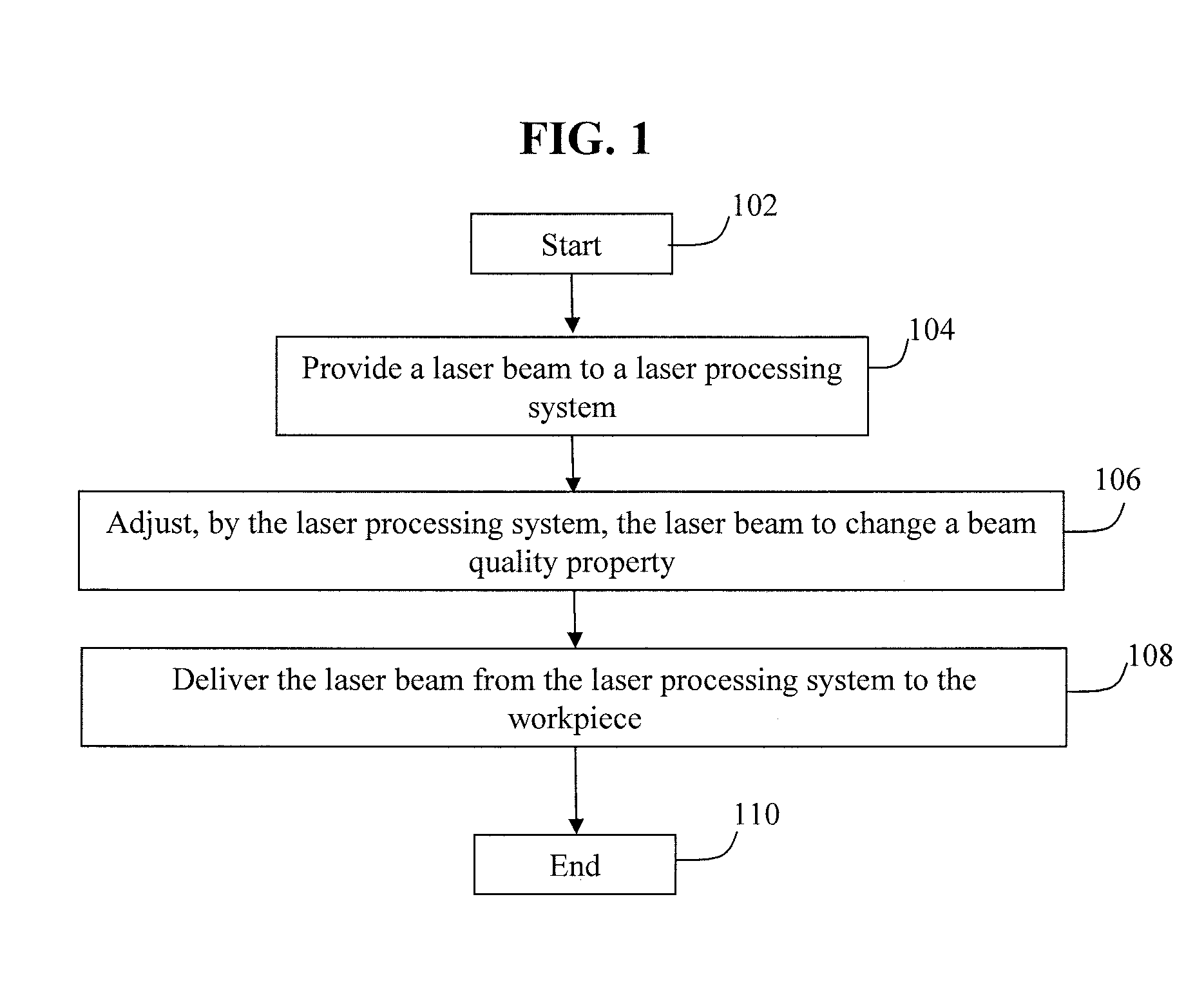
[0023]FIG. 1 shows an exemplary process for adjusting a laser beam applied to a workpiece in a material processing operation. The process starts (step 102) when a laser beam is delivered to a laser processing system from a laser source (step 104). The laser beam is associated with a beam quality property. The laser processing system can adjust the laser beam to change the beam quality property (106). In some embodiments, the beam quality property can be adjusted based on a characteristic of the workpiece (e.g., a thickness of the workpiece), a characteristic of the processing operation, or a combination thereof (step 106). The process ends (step 110) when, after the laser processing system makes the appropriate adjustments to the laser beam, the laser beam is delivered to the workpiece to produce a more desired laser energy distribution on the workpiece, such as along the kerf of a cut (step 108).

[0024]The beam quality defines how tightly a laser beam can be focused for a fixed beam...


PUM

PropertyMeasurementUnit
Thicknessaaaaaaaaaa
Angleaaaaaaaaaa

Abstract

Systems and methods are provided for adjusting a laser beam applied to a workpiece in a processing operation. A laser processing system receives the laser beam that is associated with a beam quality property. The laser processing system adjusts the laser beam to change the beam quality property based on a characteristic of the workpiece, a characteristic of the processing operation, or a combination thereof. The adjusted laser beam can also be delivered to the workpiece.

Description

FIELD OF THE INVENTION[0001]The present invention relates generally to material processing using laser beams, and more particularly, to optimizing and controlling laser beam quality for material processing.BACKGROUND OF THE INVENTION[0002]Lasers are frequently used in material processing applications because laser beams can be focused to small spot sizes, thereby achieving the intensity and power density desired to process industrial-strength materials, such as metals. Exemplary processing applications include cutting, welding, surface modification, drilling and cladding. In a cutting operation, for example, it is generally desirable to focus a delivered laser beam to a small spot size so that a high intensity beam can be applied to the workpiece. This produces narrow kerf widths, high material removal rates and increased processing speed. Therefore, it is generally accepted that the higher the intensity of the applied beam, the faster the processing speed.[0003]However, the relatio...

Claims


Application Information

Patent Timeline
IPC IPC(8): B23K26/00B23K26/38B23K26/14B23K26/20B23K26/073B23K26/03
CPCB23K26/041B23K26/06B23K26/20B23K26/34G02B6/4226B23K26/38B23K26/381G02B6/4296G02B6/4206B23K26/36B23K26/042B23K26/382B23K26/21
Inventor WOODS, KENNETH J.GARG, SANJAYPICARD, TATE S.
Owner HYPERTHERM INC
Why Eureka
Try Eureka