Power supply control circuit and power source cut-off detection method

a power supply control circuit and power supply technology, applied in the direction of power supply testing, electric vehicles, transportation and packaging, etc., can solve the problems of increasing the power consumption of the switching power supply, the risk of getting an electric shock from the voltage of the electric charge, and the increase in the power conversion efficiency of the power supply, so as to reduce the power loss and reliably discharge the remaining accumulated electric charge.

Active Publication Date: 2013-06-13
FUJI ELECTRIC CO LTD
View PDF7 Cites 46 Cited by
  • Summary
  • Abstract
  • Description
  • Claims
  • Application Information

AI Technical Summary

Benefits of technology

[0038]According to embodiments of the invention, when the input circuit is not disconnected from the alternating current power source, the discharging circuit is not constantly connected, meaning that it is possible to reduce a power loss caused by a discharging resistor.
[0039]Also, according to the power source cut-off detection method of the power supply control circuit, it is possible to reliably discharge the accumulated electric charge remaining in the capacitor by detecting that the plug has been disconnected from the AC lines.
[0040]The heretofore described and other objects, features, and advantageous effects of embodiments of the invention will be clarified by the following description relating to the attached drawings illustrating preferred embodiments as examples of the invention.
[0041]Additional aspects and / or advantages will be set forth in part in the description which follows and, in part, will be apparent from the description, or may be learned by practice of the invention.

Problems solved by technology

With this method, as the discharging resistor is constantly connected to an alternating current input power source, a power loss occurs in the discharging resistor, and power consumption of the switching power supply increases, causing a decrease in power conversion efficiency.
However, although the switching power supply is disconnected from the AC lines 101, electric charge remains in the capacitors Cx1 and Cx2 of the filter circuit 102, and there is a risk of getting an electric shock from the voltage of the electric charge.
The problem here is in that, as the discharging resistor Rx is constantly connected to the AC lines 101, power conversion efficiency decreases.
A problem of the switching power supply of PTL 1 is in that the whole structure becomes large because the switch 206 is used.
Also, a particularly important problem includes a point of being short of specifics as no method of detecting that the plug 201 has been disconnected from the AC lines is disclosed.
However, with the switching power supply of FIG. 12, it is possible to reduce losses which have occurred individually, but it is not possible to eliminate a power loss completely.

Method used


Image

  • Power supply control circuit and power source cut-off detection method
  • Power supply control circuit and power source cut-off detection method
  • Power supply control circuit and power source cut-off detection method

Examples


first embodiment

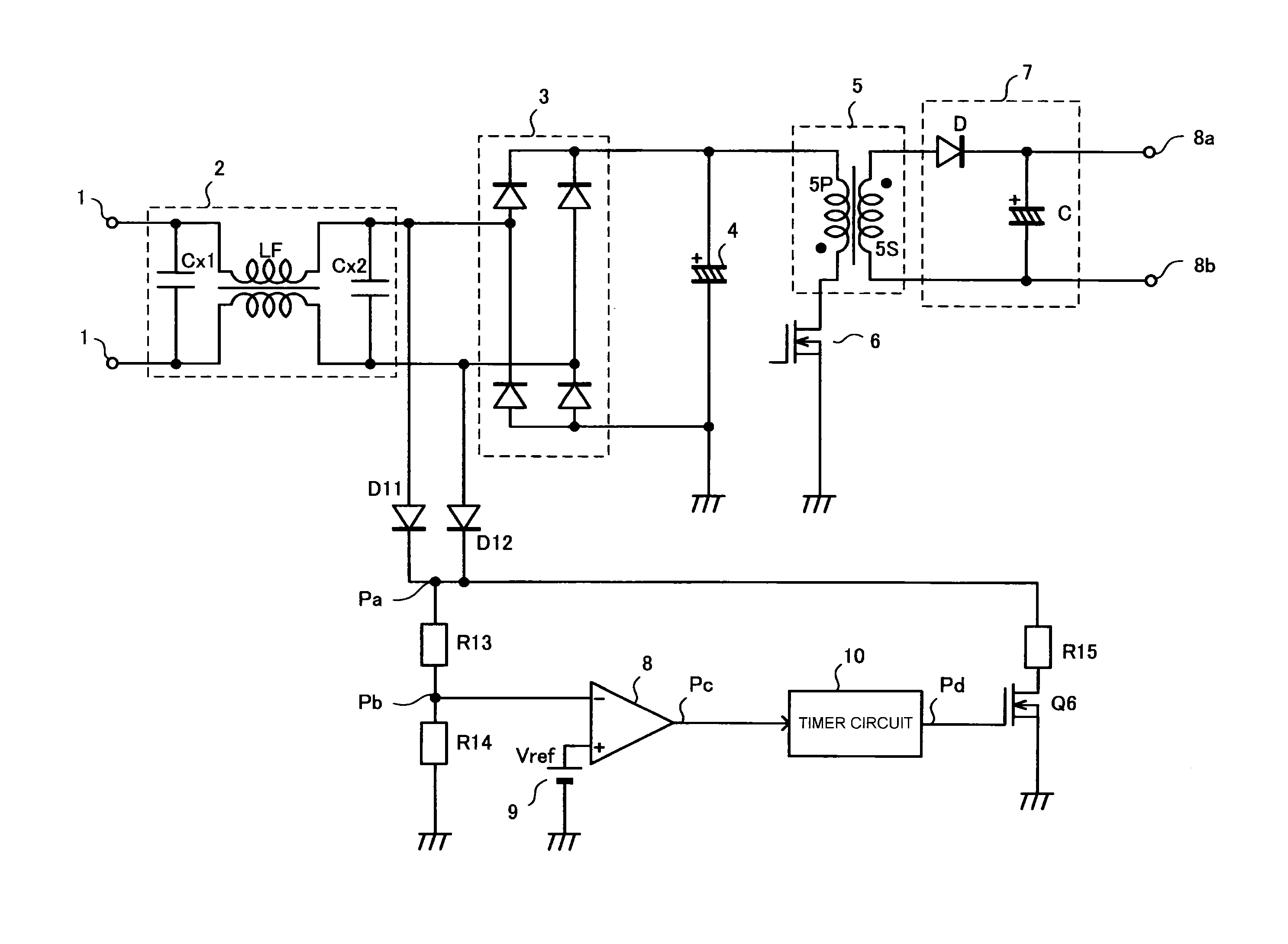
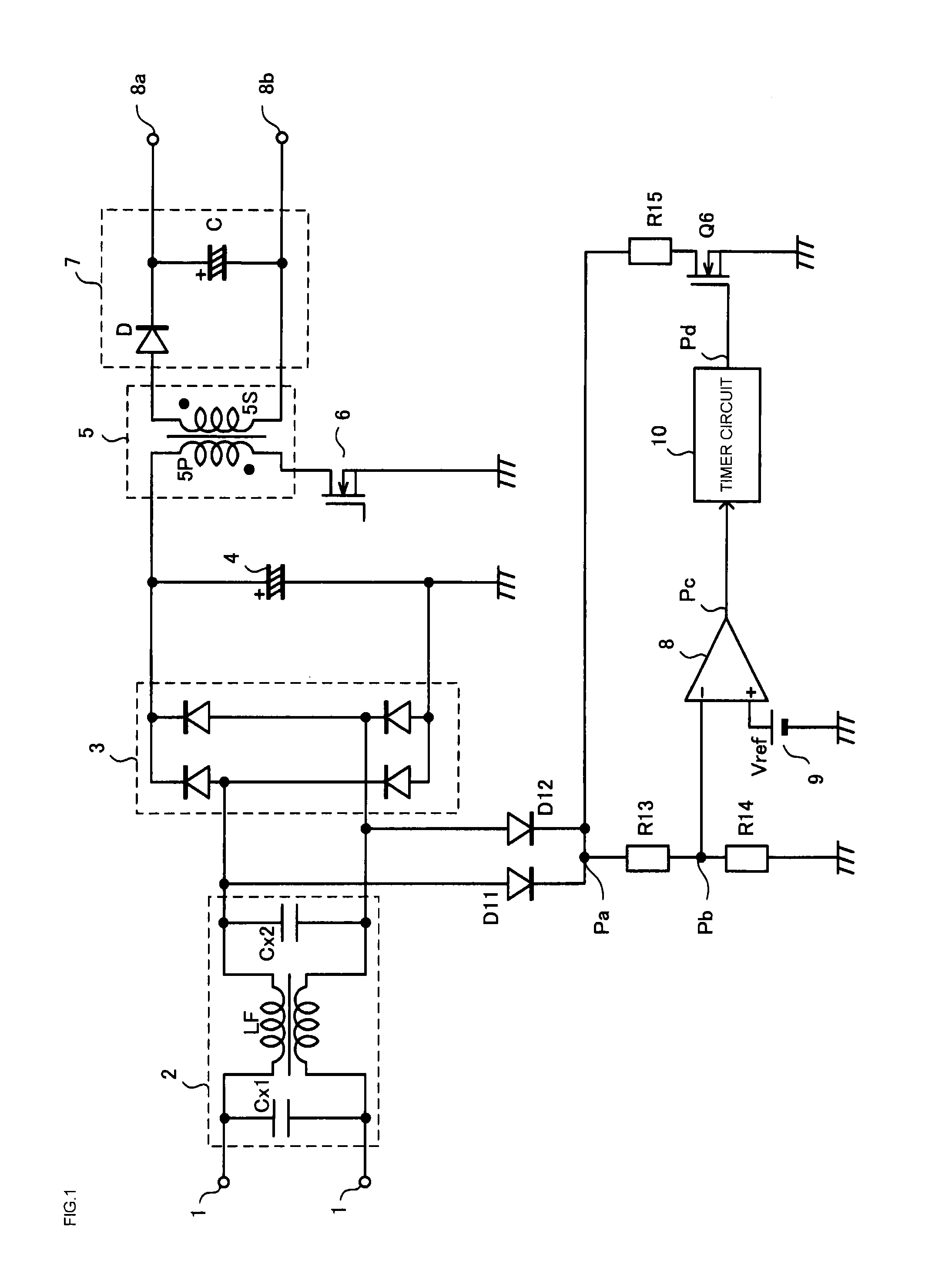
[0058]FIG. 1 is a diagram showing a configuration of a switching power supply of a first embodiment.

[0059]A rectifier circuit 3 is connected to AC lines 1 of a commercial power source via a filter circuit 2. The filter circuit 2 is configured of capacitors Cx1 and Cx2 and an inductor LF. A point differing from a heretofore known switching power supply of FIG. 10 is that no discharging resistor (Rx) is provided on the input side of the filter circuit 2.

[0060]Herein, the switching power supply is configured of an input capacitor 4 and transformer 5 connected to the output side of the rectifier circuit 3, a switching element 6 connected in series to a primary winding 5P of the transformer 5, and a smoothing circuit 7 formed of a diode D and smoothing capacitor C connected to a secondary winding 5S of the transformer 5. Further, a turning on / off of the switching element 6 is controlled by an unshown PWM control circuit, thereby supplying a predetermined direct current voltage to a load ...

modification example

[0075]FIG. 4 is a circuit diagram showing a configuration of a modification example of the first embodiment. A point differing from the circuit configuration in the first embodiment is that a delay circuit 20 is provided between the output terminal of the timer circuit 10 and the switch element Q6.

[0076]FIG. 5 is a waveform diagram for illustrating an operation of the switching power supply of FIG. 4.

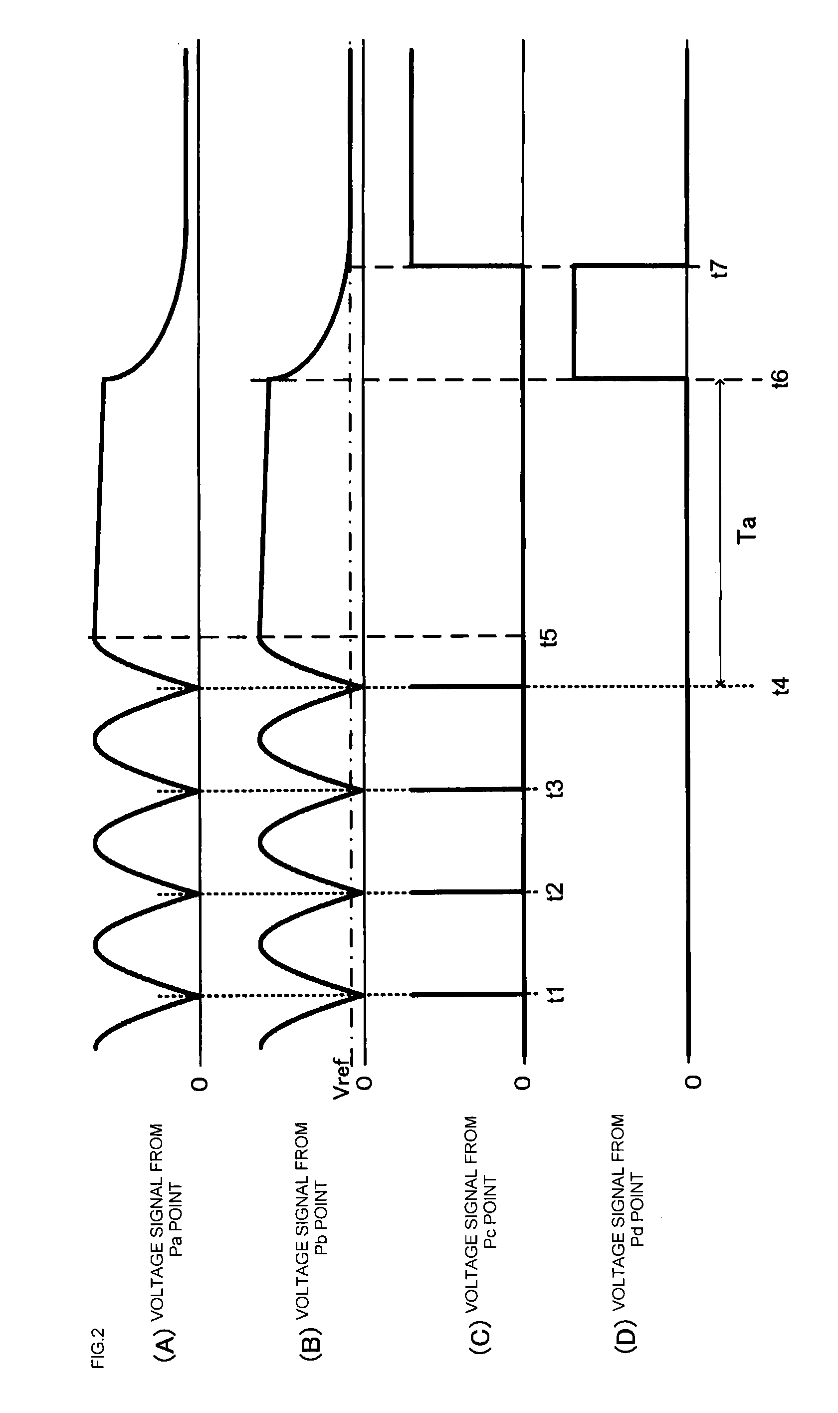
[0077]Heretofore, with a switching power supply which rectifies an alternating current power source, there has been a case in which the voltage of the connection point Pa does not lower to 0V due to the influence of parasitic capacitance associated with each of wiring lines connected to the diodes D11 and D12, resistors R13, R14, and R15, switch element Q6, and connection points Pa and Pb, or the like. That is, there has been a case in which the voltages of the connection points Pa and Pb increase and decrease in accordance with an increase and decrease in input circuit capacitor termin...

second embodiment

[0079]FIG. 6 is a diagram showing a configuration of a switching power supply of a second embodiment.

[0080]The switching power supply is configured so that a comparator 8 and a timer circuit 10 are incorporated in a control circuit (a power supply control circuit) 30. A full-wave rectified waveform of an alternating current power source is supplied to a VH terminal of the integrated circuit 30 via diodes D11 and D12. A PWM control circuit 31 which controls a switching element 6, a start circuit 32 which generates drive power at a power source starting time, and a start control circuit 33 are also configured in the control integrated circuit 30. As the external terminal of the integrated circuit 30, a DO terminal is connected to the gate of the switching element 6 via a resistor R17. Also, a VCC terminal, as well as being grounded via a capacitor C8, is connected to the cathode of a diode D13. The anode of the diode D13 is connected to one end of an auxiliary winding 5C of a transfor...


PUM


Abstract

A power supply control circuit arranged to prevent a steady power loss from occurring in an input filter connected to an alternating current power source. In order to detect that an AC input has been turned off, diodes are connected to AC lines, thus detecting a full-wave rectified waveform. This detected voltage is compared with a reference voltage by a comparator. An output signal of the comparator is input into the reset terminal of a timer circuit having a time measurement period longer than the power source frequency of an alternating current power source. A switch element of a discharging circuit is turned on by an output signal of the timer circuit.

Description

CROSS-REFERENCE TO RELATED APPLICATIONS[0001]This application is a continuation application, filed under 35 U.S.C. §111(a), of International Application PCT / JP2011 / 070345 filed on Sep. 7, 2011, and claims the foreign benefit of Japanese Application No. 2010-202903, filed Sep. 10, 2010 in the Japanese Intellectual Property Office and Japanese Application No. 2011-072037, filed Mar. 29, 2011 in the Japanese Intellectual Property Office, the disclosures of all of which are incorporated herein by reference.BACKGROUND[0002]1. Field[0003]Embodiments of the present invention relate to a power supply control circuit connected to an alternating current power source via an input circuit having a capacitor, a power source cut-off detection method, and, particularly, a power supply control circuit and power source cut-off detection method such that a discharge of the capacitor is carried out when cutting off the alternating current power source.[0004]2. Description of the Related Art[0005]A pow...

Claims


Application Information

Patent Timeline
Patent Type & Authority Applications(United States)
IPC IPC(8): H02M7/02
CPCG01R31/40H02M1/32H02M7/02H02M2001/322H02M7/217H02M1/126H02M1/322
Inventor SHIROYAMA, HIRONOBUSUGAWARA, TAKATO
Owner FUJI ELECTRIC CO LTD
Why Eureka
Try Eureka