Method of regenerating diffraction signals for optical metrology systems

a technology of optical metrology and diffraction signal, applied in the field of optical metrology system, can solve the problems of insufficient assumptions used in modeling the optical metrology tool, and affecting the accuracy of measurement. , to achieve the effect of enhancing the accuracy of the optical metrology system

Inactive Publication Date: 2013-06-13
TOKYO ELECTRON LTD
View PDF5 Cites 15 Cited by
  • Summary
  • Abstract
  • Description
  • Claims
  • Application Information

AI Technical Summary

Benefits of technology

[0009]Provided is a method for enhancing accuracy of an optical metrology system that includes a metrology tool, an optical metrology model, and a profile extraction algorithm. The optical metrology model includes a model of the metrology tool and a profile model of the sample structure, the profile model having profile parameters. A library comprising Jones and / or Mueller matrices and / or components (JMMOC) and corresponding profile parameters is generated using ray tracing and a selected range of beam propagation parameters. An original simulated diffraction signal is calculated using the optical metrology model. A regenerated simulated diffraction signal is obtained using the regenerated JMMOC, integrated for all the rays of the optical metrology model. If an error and precision criteria for the regenerated simulated diffraction signal compared to the original simulated diffraction signal are met, one or more profile parameters are determined from the best match regenerated simulated diffraction signal.

Problems solved by technology

In terms of measurement uncertainty, as the size of the structures get smaller, complicated interactions between the optical metrology tool properties vary in complex ways to affect the accuracy of the measurement.
For example, as the lithography node gets smaller, errors associated with critical dimension and sample structure profile extraction are the larger errors to be considered.
Furthermore, assumptions used in modeling the optical metrology tool are no longer sufficient.
In ray tracing, when the number of rays is increased, the length of time to create a library and the size of the library can be problematic.

Method used


Image

  • Method of regenerating diffraction signals for optical metrology systems
  • Method of regenerating diffraction signals for optical metrology systems
  • Method of regenerating diffraction signals for optical metrology systems

Examples


Embodiment Construction

[0025]In order to facilitate the description of the present invention, a semiconductor wafer or substrate may be utilized to illustrate an application of the concept. The systems and processes equally apply to other workpieces that have repeating structures. The workpiece may be a wafer or substrate, a substrate, disk, or the like. Furthermore, in this application, the term structure when it is not qualified refers to a patterned structure. Moreover, the term structure and sample structure are used interchangeably and refer to the same item. The sample structure can be a grating, a three-dimensional repeating structure, or the like.

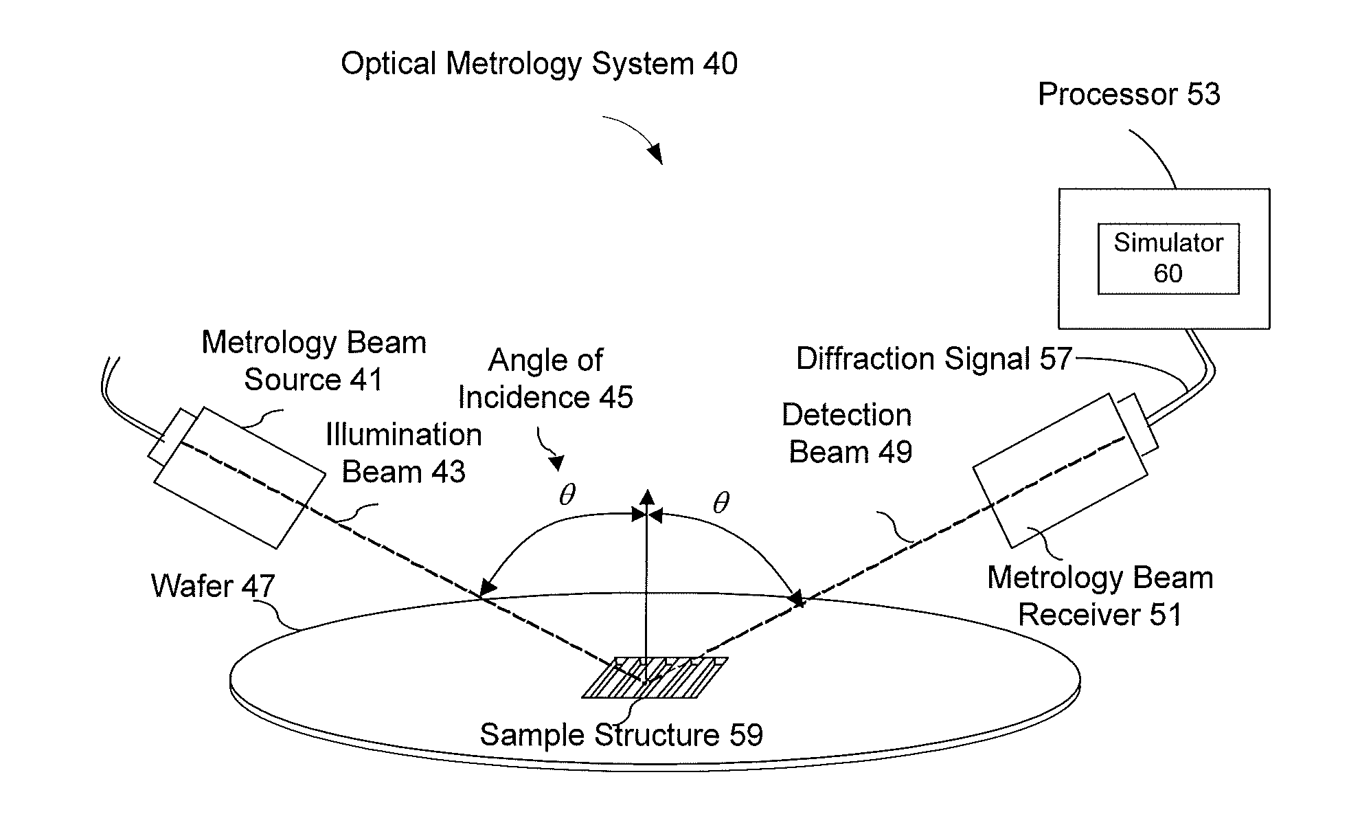
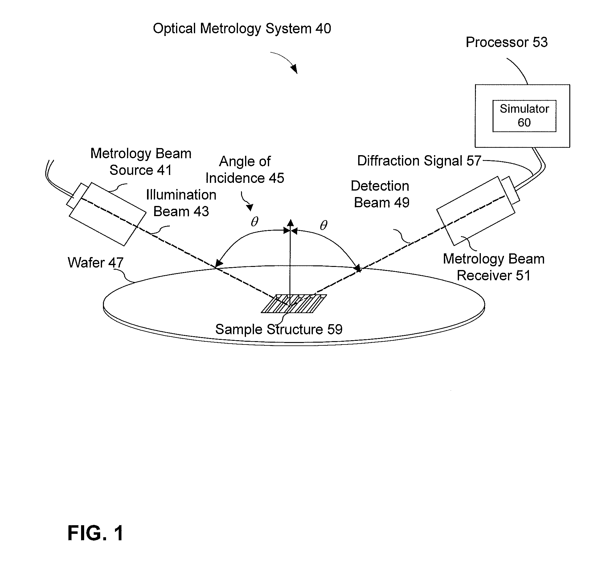
[0026]FIG. 1 is an architectural diagram illustrating an exemplary embodiment where optical metrology can be utilized to determine the profiles or shapes of structures fabricated on a semiconductor wafer or substrate. The optical metrology system 40 includes a metrology beam source 41 projecting a metrology illumination beam 43 at the sample structure 59 ...


PUM


Abstract

Provided is a method for enhancing accuracy of an optical metrology system that includes a metrology tool, an optical metrology model, and a profile extraction algorithm. The optical metrology model includes a model of the metrology tool and a profile model of the sample structure, the profile model having profile parameters. A library comprising Jones and / or Mueller matrices and / or components (JMMOC) and corresponding profile parameters is generated using ray tracing and a selected range of beam propagation parameters. An original simulated diffraction signal is calculated using the optical metrology model. A regenerated simulated diffraction signal is obtained using the regenerated JMMOC, integrated for all the rays of the optical metrology model. If an error and precision criteria for the regenerated simulated diffraction signal compared to the original simulated diffraction signal are met, one or more profile parameters are determined from the best match regenerated simulated diffraction signal.

Description

BACKGROUND[0001]1. Field[0002]The application generally relates to the use of an optical metrology system to measure a sample structure formed on a workpiece, and, more particularly, to a method and a system for regenerating diffraction signal optical metrology systems.[0003]2. Related Art[0004]Optical metrology involves directing an incident beam at a sample structure on a workpiece, measuring the resulting diffraction signal, and analyzing the measured diffraction signal to determine various characteristics of the sample structure. The workpiece can be a wafer, a substrate, photomask or a magnetic medium. In manufacturing of the workpieces, periodic gratings are typically used for quality assurance. For example, one typical use of periodic gratings includes fabricating a periodic grating in proximity to the operating structure of a semiconductor chip. The periodic grating is then illuminated with an electromagnetic radiation. The electromagnetic radiation that deflects off of the ...

Claims


Application Information

Patent Timeline
Patent Type & Authority Applications(United States)
IPC IPC(8): G06F15/18G06F17/10
CPCG01N21/956G01N21/9501
Inventor LI, SHIFANG
Owner TOKYO ELECTRON LTD
Why Eureka
Try Eureka