Programmable Fault Protect for Processor Controlled High-Side and Low-Side Drivers

a technology of processor control and fault protection, applied in the direction of instruments, coding, code conversion, etc., can solve the problems of time and money invested in learning about a previously selected microcontroller, and the inability to meet the new needs of the evolving system,

Active Publication Date: 2013-06-13
ACTIVE SEMI
View PDF1 Cites 61 Cited by
  • Summary
  • Abstract
  • Description
  • Claims
  • Application Information

AI Technical Summary

Benefits of technology

[0005]A Multi-Tile Power Management Integrated Circuit (MTPMIC) includes a plurality of Power Management Integrated Circuit (PMIC) tiles. In one example, these PMIC tiles include an MCU / ADC tile, a driver manager tile, a power manager tile, and a signal manager tile. The PMIC tiles when joined together as parts of the MTPMIC form a standardized bus. Each tile has functional circuitry and a configuration register. Configuration information in the configuration register of a tile determines how the functional circuitry of the tile is configured. A processor in the MCU / ADC tile is coupled to the standardized bus. This processor can write across the standardized bus to the configuration register in any desired one of the tiles and in this way can configure and reconfigure the functional circuitry in the various tiles.
[0008]During switching of the switching power supply, the CSPSPWM causes a main switch of the switching power supply to be pulsed on in a safe start-up mode. In the safe start-up mode, the main switch is pulsed on at a constant fixed low switching frequency and with pulses that have a fixed on time. As the switching power supply operates in this safe mode, the supply voltage VP on the terminal VP rises. During this time, the CSPSPWM determines the current sensing method based on how circuitry external to the integrated circuit is configured and operates. The supply voltage VP on the terminal VP is the output supply voltage of the switching power supply. After a short time of operation in the safe mode, the supply voltage VP present on the terminal VP is high enough that the CSPSPWM is made to operate in a normal operating mode. In the normal operating mode, the main external switch is controlled to switch at a higher switching frequency (higher than in the start-up mode) and with pulse width modulated on time.

Problems solved by technology

Although engineers with backgrounds in microcontroller programming are generally capable of designing and building simple circuits that can provide power to such a microcontroller if the microcontroller is operating by itself, the skill set of such engineers generally does not include experience designing more complex switching power supplies of the types suitable for supplying power to the overall microcontroller controlled system.
Moreover, the selection of the best microcontroller for the application can be a challenging task.
If the selection of a particular microcontroller family is made, and later changes in function of the system is necessary, then the microcontroller family initially selected may not be able to satisfy the new needs of the evolving system.
Time and money invested in learning about a previously selected microcontroller may be wasted if the microcontroller at the heart of the system must be changed.

Method used


Image

  • Programmable Fault Protect for Processor Controlled High-Side and Low-Side Drivers
  • Programmable Fault Protect for Processor Controlled High-Side and Low-Side Drivers
  • Programmable Fault Protect for Processor Controlled High-Side and Low-Side Drivers

Examples


Embodiment Construction

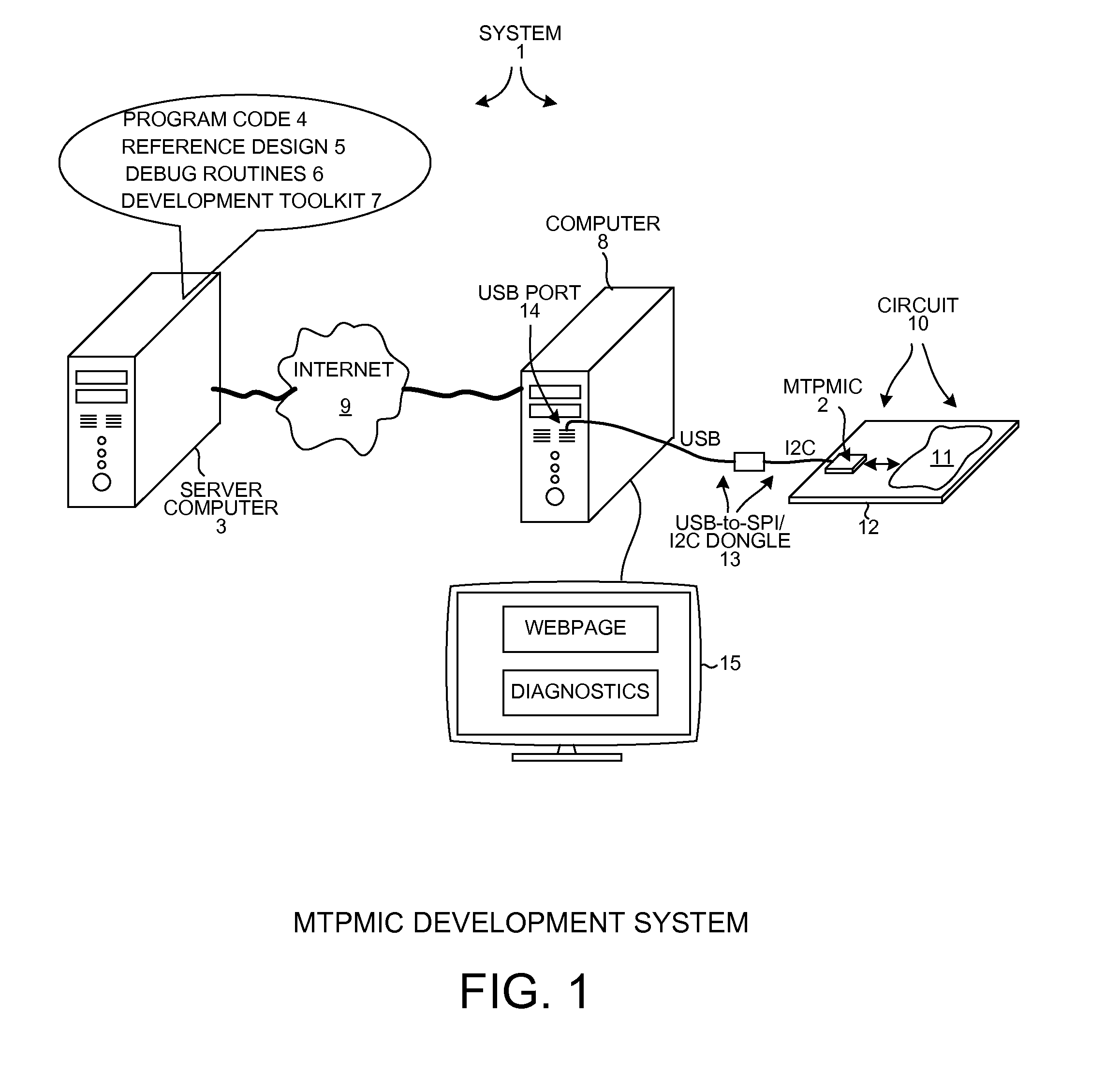
[0036]FIG. 1 is a diagram of a system 1 involving a Multi-Tile Power Management Integrated Circuit (MTPMIC) 2. A server 3 stores an amount of program code 4, information 5 on a reference design that uses the MTPMIC 2, debug routines 6, and development toolkit software 7. Server 3 may store a great number of reference designs using the MTPMIC2, where each reference design and the associated program code has been thoroughly verified by a power supply company that manufacturers MTPMIC 2 and that operates server 3.

[0037]A computer 8 is coupled via the internet 9 to server 3. A user uses computer 8 to access a website served by server 3 and to download from the website the information about MTPMIC 2 and about a reference design. Using this information, the user then fabricates the reference design or another user specific circuit based on the reference design. In the present example, the circuit 10 that the user fabricates is the reference design. The circuit 10 includes MTPMIC 2 and an ...


PUM


Abstract

A Multi-Tile Power Management Integrated Circuit (MTPMIC) includes a processor, a fault protect circuit, a first terminal, a driver that drives the first terminal, a second terminal, and detection circuitry that outputs a digital detection signal indicative of whether a predetermined condition is detected on the second terminal. The processor can program the fault protect circuit so that the fault protect circuit will later disable the driver as a function of multiple signals, including the digital detection signal. The function is programmable by the processor. In one example, if the detection circuitry detects the predetermined condition on the second terminal then the fault protect circuit disables all the high-side drivers and all low-side drivers of the MTPMIC independently of and without input from the processor.

Description

CROSS REFERENCE TO RELATED APPLICATION[0001]This application is a continuation-in-part of, and claims priority under 35 U.S.C. §120 from, nonprovisional U.S. patent application Ser. No. 13 / 315,282 entitled “Power Manager Tile For Multi-Tile Power Management Integrated Circuit,” filed on Dec. 8, 2011, the subject matter of which is incorporated herein by reference.TECHNICAL FIELD[0002]The present disclosure relates generally to power management integrated circuits.BACKGROUND INFORMATION[0003]There are a many varieties of microcontroller integrated circuits that are useable in power switching and power control applications. Existing microcontrollers typically involve a processor along with relatively simple general purpose input / output terminals and perhaps an Analog-to-Digital Converter (ADC) and / or a Digital-to-Analog Converter (DAC). To use such a microcontroller in the overall power control system, some sort of power supply is generally necessary to generate a supply voltage from ...

Claims


Application Information

Patent Timeline
Patent Type & Authority Applications(United States)
IPC IPC(8): G06F11/07
CPCG06F1/26H02M1/32Y02B20/341H05B33/0887H02M2001/0012Y02B20/30H02M1/0012
Inventor HUYNH, STEVEN
Owner ACTIVE SEMI
Why Eureka
Try Eureka