Pyrotechnic High Voltage Battery Disconnect

a high-voltage battery and high-voltage technology, applied in the field of vehicles, can solve the problems of inability to program inability to respond to different types of events, and inability to detect directionality relative insensitive sensors

Active Publication Date: 2013-06-20
TESLA INC
View PDF1 Cites 76 Cited by
  • Summary
  • Abstract
  • Description
  • Claims
  • Application Information

AI Technical Summary

Benefits of technology

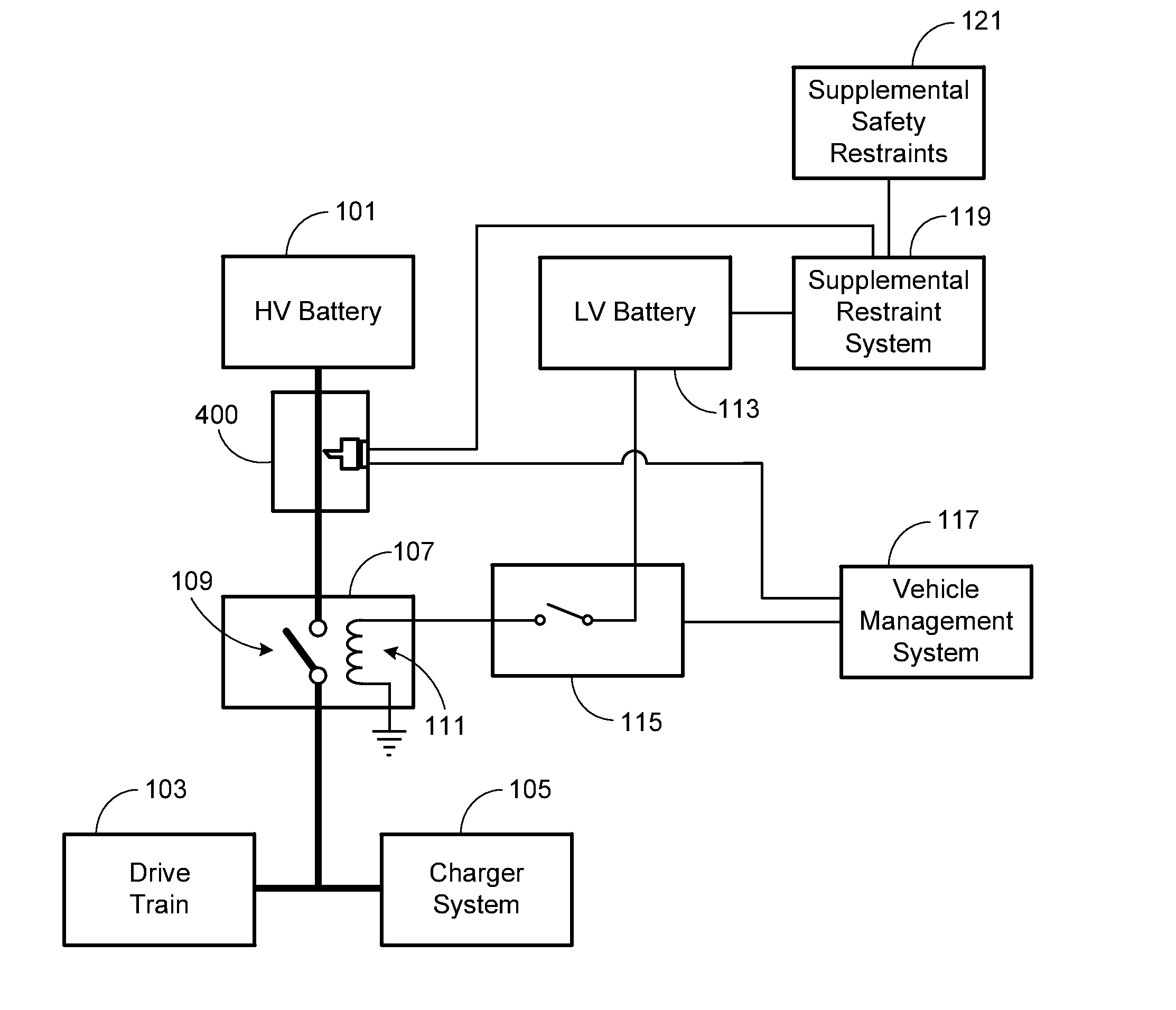
[0008]The system may include a low voltage (LV) power source, where upon receipt of the supplemental restraint activation signal an LV pulse is transmitted to a pyrotechnic initiator corresponding to the pyrotechnic switch, causing the pyrotechnic switch to sever the conductive path and prevent the HV source from being electrically connected to the vehicle's electrical system.

Problems solved by technology

Additionally, while the housing used to package a multi-cell vehicle battery must be structurally sound enough to allow battery pack inspection and / or replacement, it must do so with minimal weight since hybrids and electric cars are exceptionally sensitive to excess weight.
Thermal runaway may be initiated by a short circuit within the cell, improper cell use, physical abuse, manufacturing defects, or exposure of the cell to extreme external temperatures.
Given that a thermal runaway event can lead to significant property damage and, in some circumstances, bodily harm or loss of life, the battery systems used in most all-electric or hybrid vehicles employ one or more means of preventing, detecting and mitigating the effects of such an event.
While there are a variety of systems and techniques that may be used to protect the batteries with a vehicle's battery pack as well as the vehicle's occupants during normal vehicle use, it will be appreciated that a vehicle collision presents an extremely difficult challenge given the limited control afforded by such an event.
Additionally, such sensors are relatively insensitive to directionality and are not capable of being programmed to respond differently to different types of events.

Method used


Image

  • Pyrotechnic High Voltage Battery Disconnect
  • Pyrotechnic High Voltage Battery Disconnect
  • Pyrotechnic High Voltage Battery Disconnect

Examples


Embodiment Construction

[0023]In the following text, the terms “battery”, “cell”, and “battery cell” may be used interchangeably and may refer to any of a variety of different cell types, chemistries and configurations including, but not limited to, lithium ion (e.g., lithium iron phosphate, lithium cobalt oxide, other lithium metal oxides, etc.), lithium ion polymer, nickel metal hydride, nickel cadmium, nickel hydrogen, nickel zinc, silver zinc, or other battery type / configuration. The term “battery pack” as used herein refers to multiple individual batteries contained within a single piece or multi-piece housing, the individual batteries electrically interconnected to achieve the desired voltage and capacity for a particular application. The term “electric vehicle” as used herein may refer to an all-electric vehicle, also referred to as an EV, a plug-in hybrid vehicle, also referred to as a PHEV, or a hybrid vehicle, also referred to as a HEV, where a hybrid vehicle refers to a vehicle utilizing multipl...


PUM


Abstract

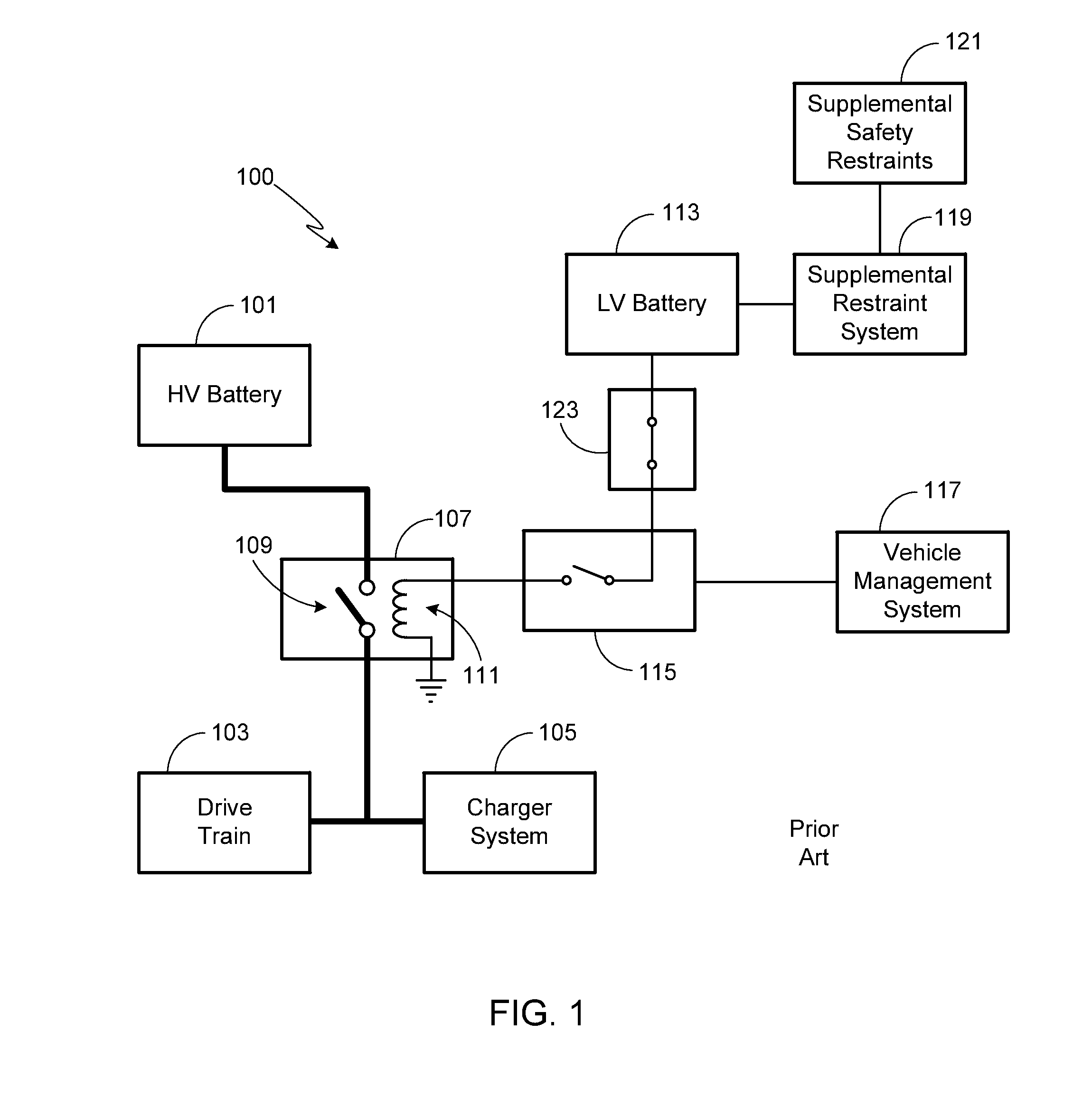
A system for decoupling a HV source from an electric vehicle's electrical system is provided that includes (i) at least one electrical contactor, where the HV source is electrically connected to the vehicle's electrical system when the electrical contactor is in a closed state and not electrically connected to the vehicle's electrical system when the electrical contactor is in an open state; (ii) a supplemental restraint system (SRS) that monitors collision data from a plurality of impact sensors and outputs an activation signal in response to monitored collision data; and (iii) a pyrotechnic switch, where the pyrotechnic switch has a pre-activated first state that provides a conductive path that allows the HV source to be electrically connected to the vehicle's electrical system and an activated second state that severs the conductive path and prevents the HV source from being electrically connected to the vehicle's electrical system.

Description

CROSS-REFERENCE TO RELATED APPLICATION[0001]This application claims the benefit of the filing date of U.S. Provisional Patent Application Ser. No. 61 / 576,440, filed 16 Dec. 2011, the disclosure of which is incorporated herein by reference for any and all purposes.FIELD OF THE INVENTION[0002]The present invention relates generally to vehicles and, more particularly, to a means of disconnecting the high voltage battery system of a vehicle in the event of a catastrophic event.BACKGROUND OF THE INVENTION[0003]The battery system used in a conventional all-electric or hybrid vehicle is required to store large amounts of energy within the confines of a relatively small battery enclosure. In addition to housing tens to thousands of individual cells in order to meet the power requirements of such a vehicle, this type of battery pack must be capable of surviving the inherent thermal and mechanical stresses of a car for a period of years. Additionally, while the housing used to package a multi...

Claims


Application Information

Patent Timeline
Patent Type & Authority Applications(United States)
IPC IPC(8): B60L1/00
CPCB60L3/04B60L3/0046B60L58/10Y02T10/70B60R21/00H01H39/006
Inventor TOKARZ, NICHOLAS PAULGOPAL, MADAN
Owner TESLA INC
Why Eureka
Try Eureka