High Conductivity Electrostatic Chuck

a high-conductivity, electrostatic chuck technology, applied in the direction of electrostatic holding devices, metal-working machine components, manufacturing tools, etc., can solve the problems of workpiece “sticking” problems, large charge accumulation, and inability to release workpieces

Active Publication Date: 2013-06-20
ENTEGRIS INC +1
View PDF9 Cites 25 Cited by
  • Summary
  • Abstract
  • Description
  • Claims
  • Application Information

AI Technical Summary

Problems solved by technology

Charge accumulation can cause workpiece “sticking” problems.
In one instance, the charge accumulation can be so great that typical unclamping forces can not release the workpiece.
When an associated robot arm attempts to retrieve the wafer, it may not properly engage the wafer and even push the wafer off the platen leading to possible wafer damage and interruptions in processing.
With some circular or disk shaped workpieces such as a semiconductor wafer, the wafer may enter into a general oscillatory precession around the outer circumference of the platen creating great risk for dropping of the wafer.
In other cases, “wafer walk” may occur, which may be caused by partial sticking of the wafer edge to the platen during lifting, resulting in a wobble of the wafer on the lift pins and possible misalignment on the pins leading to a wafer handling problem.
Even if charge accumulation does not lead to workpiece “sticking” problems, it may lead to damage of devices being formed on the workpiece.
In a plasma doping ion implanter where the workpiece is positioned in the same chamber as plasma, excessive charge accumulation can also lead to doping non-uniformities, micro-loading, and arcing.
Hence, the throughput of the plasma doping ion implanter may be intentionally limited in some instances to avoid excessive charge accumulation.
One drawback of this solution is that the spring loaded grounding pins are limited to three pins.
As such, the effectiveness of this grounding arrangement to dissipate excessive charge build up is limited.
Another drawback of this solution is that the contact points of the spring loaded grounding pins have sharp edges that can cause damage to the backside of the workpiece.
Damage to the backside of the workpiece can also generate unwanted particles (contamination) which may be critical to limit in some processing applications.

Method used


Image

  • High Conductivity Electrostatic Chuck
  • High Conductivity Electrostatic Chuck
  • High Conductivity Electrostatic Chuck

Examples


Embodiment Construction

[0026]A description of example embodiments of the invention follows.

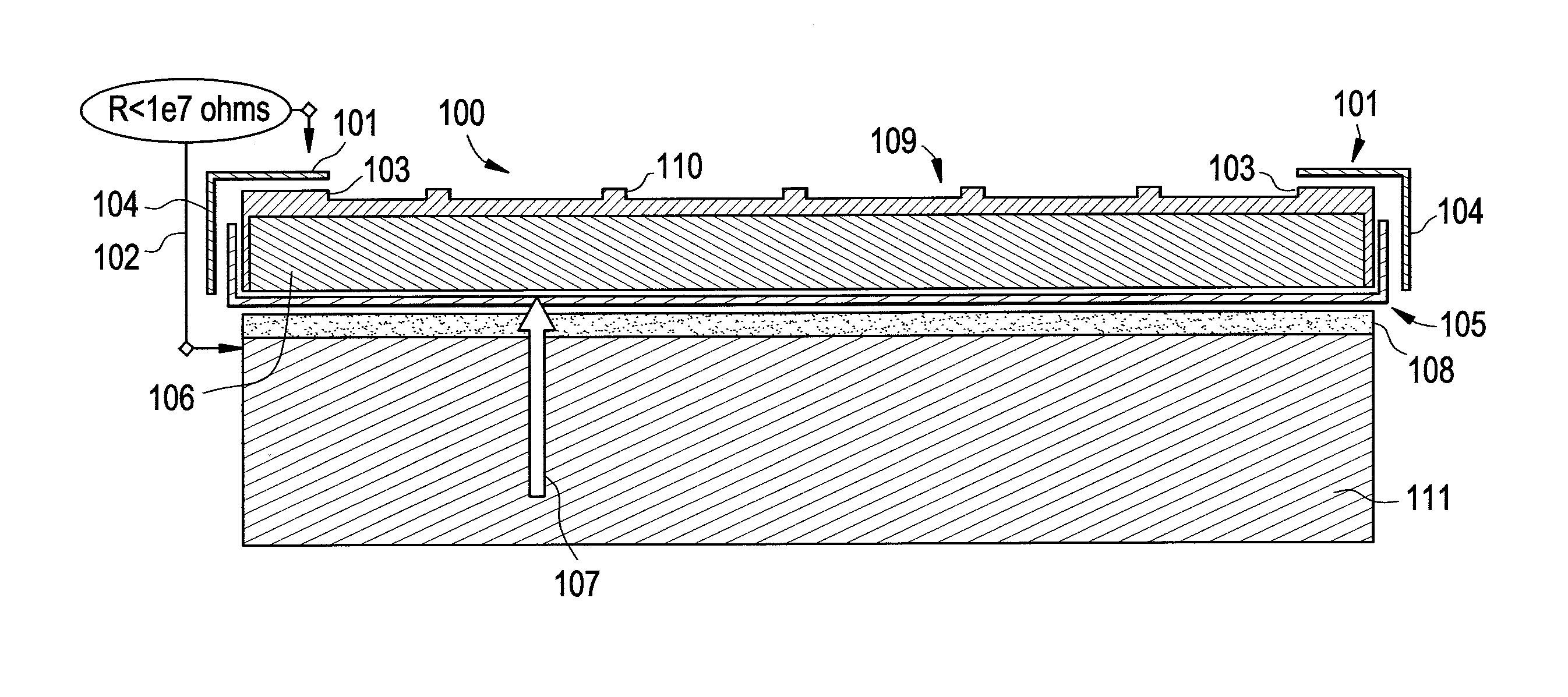
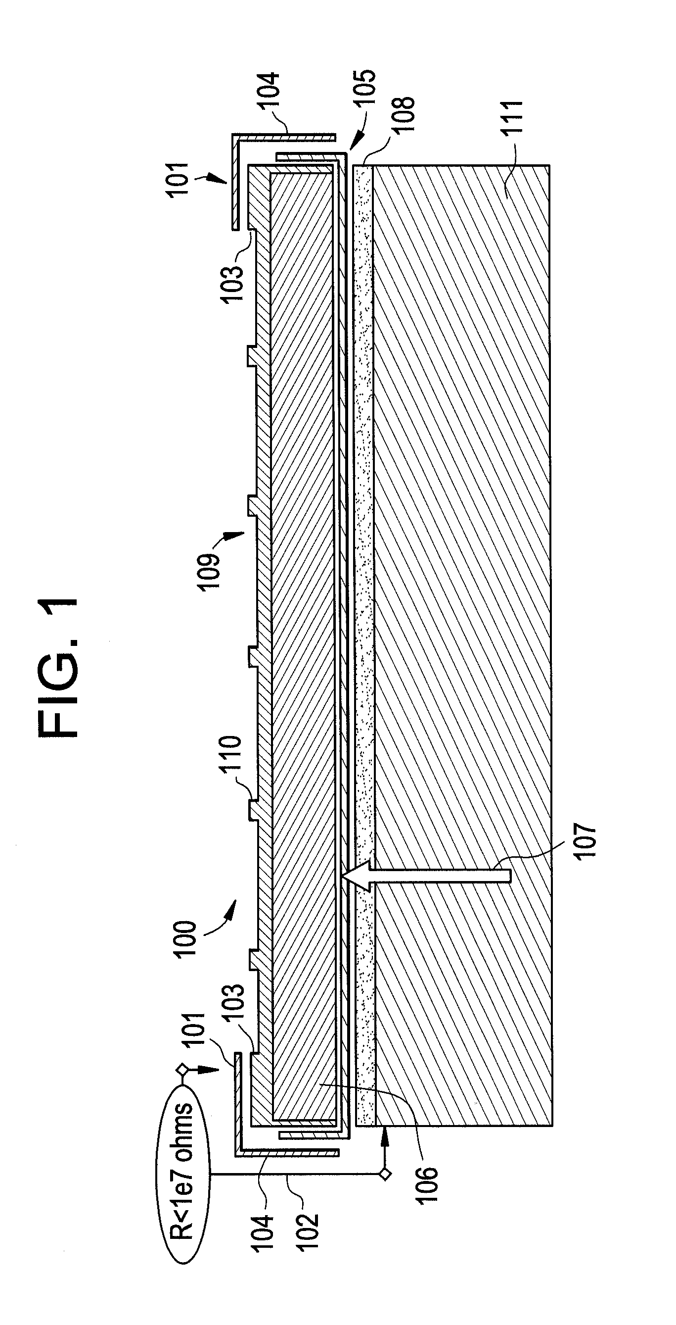
[0027]In some conventional electrostatic chucks, after numerous workpiece clamping cycles, the top surface may break down, thereby creating “islands.” Between these “islands”, the material cross sectional area may be decreased, restricting the distribution of electrical charge throughout the top doped layer. Subsequently, this creates “islands of electrical charge” where the charge polarity can be observed to reverse over several millimeters. A change of + / −400V or more over a 4-6 millimeter distance is not uncommon. This localized surface charge may lead to unintended wafer clamping even in the absence of external electrical voltage.

[0028]Accordingly, there is a need for an improved platen to control charge accumulation in electrostatic chucks.

[0029]FIG. 1 is a diagram of an electrostatic chuck 100 in accordance with an embodiment of the invention. The electrostatic chuck 100 features a conductive path to ground 10...


PUM


Abstract

In accordance with an embodiment of the invention, there is provided an electrostatic chuck comprising a conductive path covering at least a portion of a workpiece-contacting surface of a gas seal ring of the electrostatic chuck, the conductive path comprising at least a portion of an electrical path to ground; and a main field area of a workpiece-contacting surface of the electrostatic chuck comprising a surface resistivity in the range of from about 108 to about 1012 ohms per square.

Description

RELATED APPLICATIONS[0001]This application claims the benefit of U.S. Provisional Application No. 61 / 380,970, filed on Sep. 8, 2010, and claims the benefit of U.S. Provisional Application No. 61 / 509,970, filed on Jul. 20, 2011. The entire teachings of the above applications are incorporated herein by reference.BACKGROUND OF THE INVENTION[0002]Electrostatic chucks, also known as platens, are used to secure and support a workpiece for processing. Electrostatic charge may accumulate on the workpiece and also on the platen surface supporting the workpiece. Charge accumulated on the workpiece can be transferred to the platen surface, and charge accumulated on the platen surface can be transferred to the workpiece.[0003]Charge accumulation can cause workpiece “sticking” problems. In one instance, the charge accumulation can be so great that typical unclamping forces can not release the workpiece. For example, a typical unclamping force may be provided by raising lift pins to contact the b...

Claims


Application Information

Patent Timeline
Patent Type & Authority Applications(United States)
IPC IPC(8): H02N13/00
CPCB23Q3/152H02N13/00H01L21/6831B23Q3/15H01L21/683H01L21/687H01L21/6833
Inventor SUURONEN, DAVIDSTONE, LYUDMILABLAKE, JULIANSTONE, DALE K.COOKE, RICHARD A.DONNELL, STEVENVENKATRAMAN, CHANDRA
Owner ENTEGRIS INC
Why Eureka
Try Eureka