
Electrostatic dissipative foams and process for the preparation thereof

a technology of electrostatic dissipative foam and electrostatic dissipative foam, which is applied in the field of electrostatic nanofillers, can solve the problems of static charge clinging to thin films and light fabrics, igniting flammable gases, and electrical shock to staff working on shop floors, and achieving good resilience, easy to bend, roll or fold, and the effect of preventing contact electrification

Inactive Publication Date: 2015-10-01
COUNCIL OF SCI & IND RES
View PDF6 Cites 38 Cited by
  • Summary
  • Abstract
  • Description
  • Claims
  • Application Information

AI Technical Summary

Benefits of technology

This patent aims to provide a solution for preventing contact electrification and safely dissipating surface charge, while maintaining the foam's flexibility, porosity, and good resilience. The invention also aims to control the foam's density and porosity, making it ideal for applications such as ESC / ESD-free electronic packaging, antistatic apparels, footwears, and upholstery. The conducting coating is fabricated using an improved process that allows for surface conduction while retaining the foam's physical and mechanical properties. Overall, the present invention provides an effective solution for preventing static charge and maintaining foam's flexibility.

Problems solved by technology

In contrast, the tribogenerated electrostatic charge and related potential are risky and can cause problems in many areas of industry.
Particularly, the uncontrolled electrostatic dissipation (ESD) can cause ignition of flammable gases and give electrical shocks to personnel working on shop floors.
The static charges can make thin films and light fabrics cling, attract airborne dust and debris, damage semiconductor devices and upset the operation of microelectronic equipment.
Further, considering the fact that, these days; electronic devices are being widely used in the industries, offices and homes, the uncontrolled electrostatic phenomena may cause damage to electronic devices or it may also pose serious threat to human safety / health.
The cost of damage of electronic components / devices by ESD is estimated to be of the order of billions of dollars per annum.
The conventional antistatic or static dissipative materials available in the market are either metal based (e.g. surface coating of metals, metallic stripe or wire included within a non-conductive bulk material) or filled composites (e.g. polymeric matrices consisting of conducting network of fillers like graphite, carbon black, carbon fibers, carbon nanotubes or graphene; conducting polymers; metallic particles / fibers / whiskers etc.), with associated issues that make them commercially unviable as electronic packaging material.
The explosive growth of electronics and miniaturization of devices has produced electrostatic charging (ESC) and related electrostatic discharge (ESD) as most undesirable byproduct.
ESC is a critical issue especially during the handling of sensitive electronic items (e.g. data storage devices, IC chips, medical instruments etc.) due to their susceptibility towards electrostatic discharge (ESD).
The uncontrolled ESD during transportation of hazardous chemicals may lead to explosion or fire hazards with serious threat to environment or even precious human life.
Metal based coatings or filled composites are by far the most widely used materials for ESD; however, metals possess high density, corrosion susceptibility and processing difficulties.
Similarly, carbonaceous filled compositions have disadvantages in terms of poor dispersion and agglomeration of nanofillers.
However, metal oxides coatings are brittle, susceptible to corrosion and known to have poor weathering properties e.g. poor cracks / wear resistance.
However, these composites were not flexible and belong to category of non-cellular materials with relatively higher density (>0.8 g / cm3) than lightweight foamed materials.
Further, such high resistance may be useful for antisatic application but not conform to static dissipative criteria.
However, the involved polymerization process also leads to nodular growth, wastage of conducting polymer and involvement of costly chemicals that makes the commercialization bit difficult.
Further, the strong acidic conditions involved during polymerization may adversely affect the mechanical strength of some types of fabrics.
Such large amount of PANI tends to sheds from the foam's surface leading to deterioration of conductivity with time.
Further, the dopant HCl has tendency to escape from the polymer, which not only cause undoping of coated polymer (resulting in conductivity deterioration with time) but may also adversely affect (due to extremely corrosive nature of HCl gas / vapours) the sensitive electronic components containing metallic encasing, sub-components or electronic circuitry.
Therefore, such composites cannot be used as static dissipative packing / encasing materials for metallic components or sensitive electronic items.
Nevertheless, due to corrosive nature of dopant HCl, the may not be useful for static dissipative or antistatic applications and related static charge free packagings.

Method used


Image

  • Electrostatic dissipative foams and process for the preparation thereof
  • Electrostatic dissipative foams and process for the preparation thereof
  • Electrostatic dissipative foams and process for the preparation thereof

Examples


example 1 to 5

Preparation of Polyaniline Coated Foam

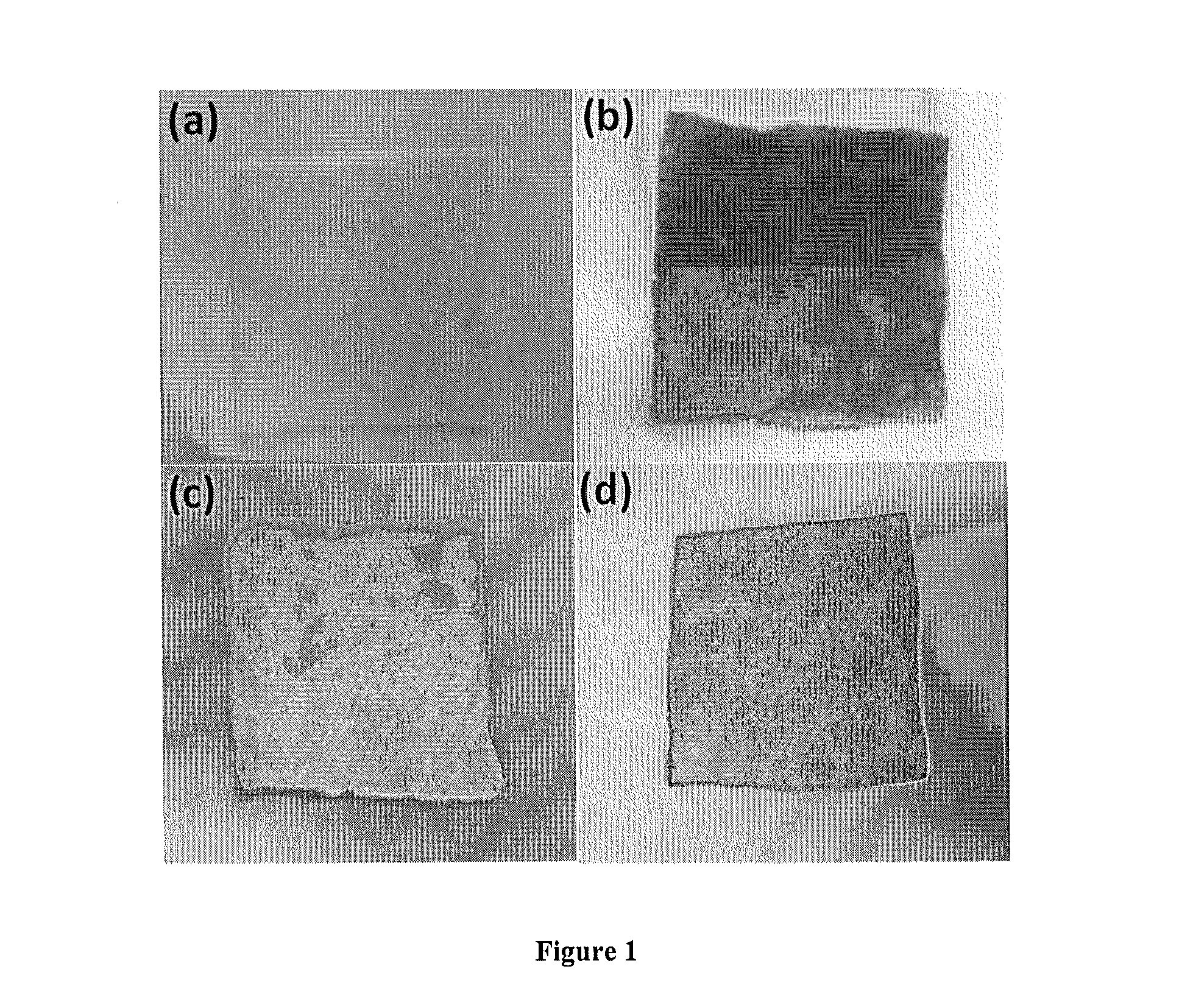
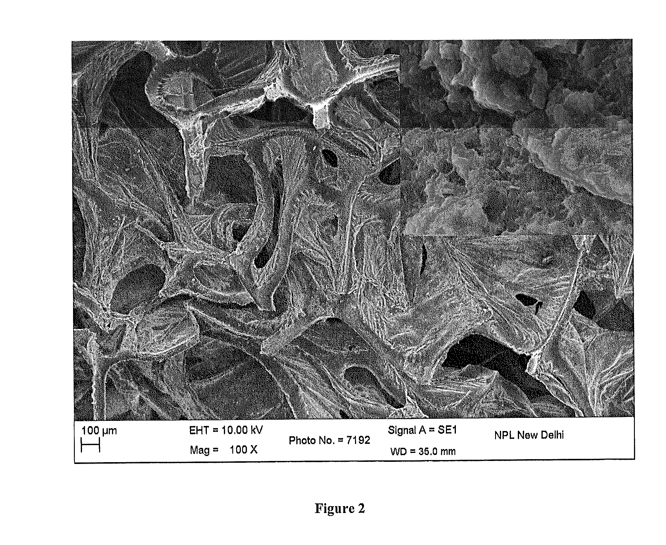
[0059]Polyaniline (PANT) decorated foam is prepared by wet chemical route using chloroform dispersion of PANI nanorods to impregnate foamed substrate followed by evaporation of chloroform leaving behind electrically conducting network of PANI nanorods over foam's surface. PANI nanorods are prepared by low temperature (−5° C.) chemical oxidative polymerization (via emulsion route) of aniline (AN) monomer in the presence of surfactant dopant i.e. dodecyl benzene sulfonic acid (DBSA).

[0060]In a typical reaction, aqueous emulsion of 0.3 M DBSA is prepared by high speed homogenization (via MICRA, D8 rotating at >10000 rpm) for 30 min, followed by addition of 0.1 mol AN (aniline) and homogenization is continued for another 30 min. Thereafter, the reaction mixture is transferred to a glass reactor, cooled to (−) 5° C. under continuous stirring and is subsequently polymerized by dropwise addition of 150 ml aqueous solution of 0.1 mol ammonium peroxydisu...

example 2

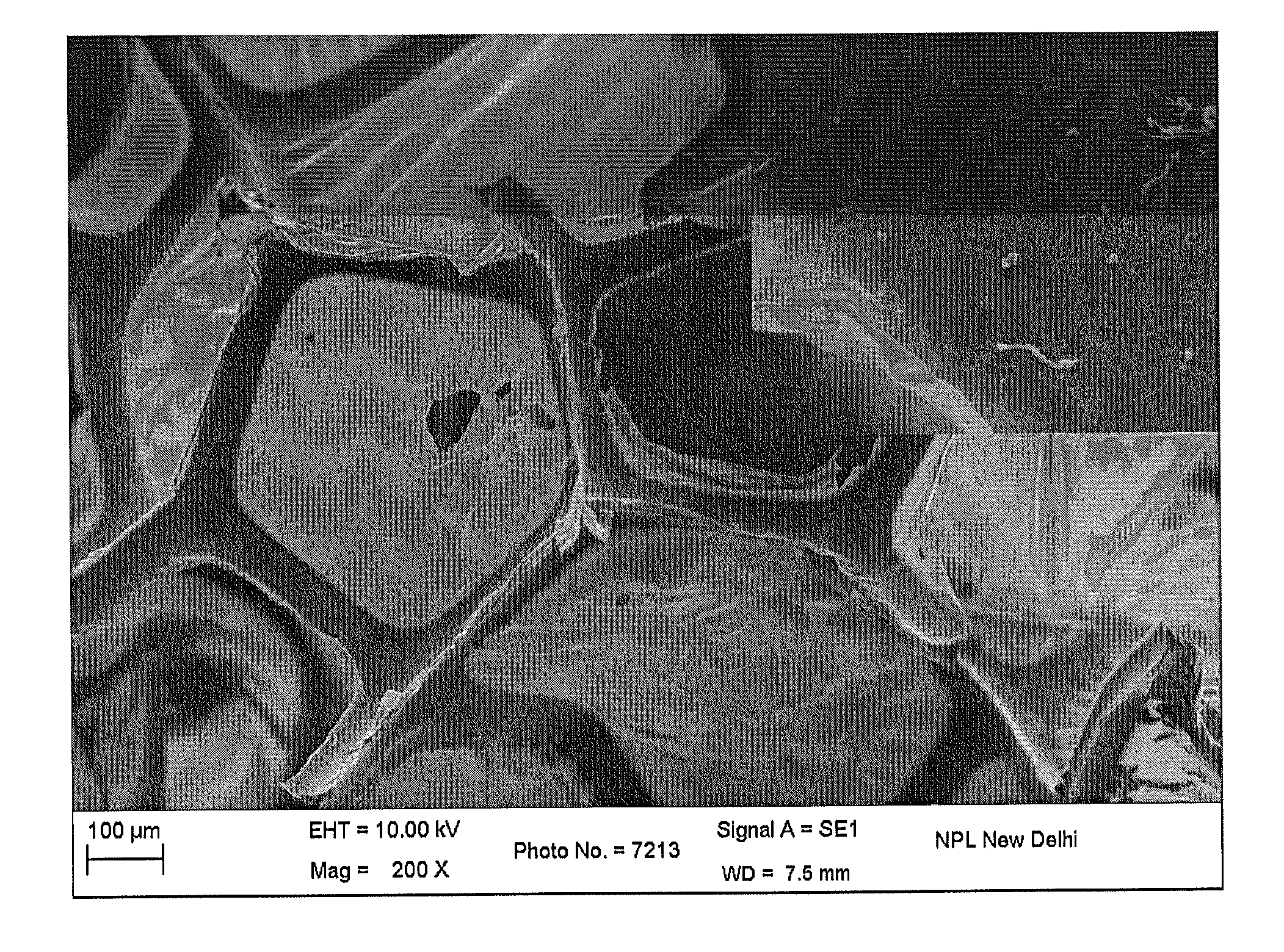
[0062]PANI nanorods decorated foam (˜0.031 volume % PANI) is prepared by wet mixing method as in example 1 by taking dilution ratio of 1:20. The coated foam display flexibility, low density and static charge dissipation capability as mentioned in Table 1. The qualification of static dissipative criteria suggests its use for making static charge dissipative (low triboelectric charging) electronic packaging / encasing material.

example 3

[0063]PANI nanorods decorated foam (˜0.055 volume % PANI) is prepared by wet mixing method as in example 1 by taking dilution ratio of 1:10. The coated foam display flexibility, low density and static charge dissipation capability as mentioned in Table 1.


PUM

PropertyMeasurementUnit
surface resistivityaaaaaaaaaa
porosityaaaaaaaaaa
densityaaaaaaaaaa

Abstract

The present invention relates to the development of electrostatic dissipative (ESD) electronic packaging materials based on the electrically conducting nanofiller decorated polyurethane foams and also describes a process for the preparation of the same. More specifically it relates to the development of electrically conducting foams by providing a coating of 0.003 to 2.97 vol % loading of electrically conducting materials (like conducting polymers, functionalized carbon nanotubes, graphene analogues etc) over / onto otherwise electrically insulating surface of foams. The combination of low density, mechanical flexibility, resilience and surface conductivity collectively contribute towards their excellent shock absorption and static charge dissipation capabilities. In particular, these foams display surface resistivity value <109 ohm / sq and static charge dissipation time <0.5 sec, which clearly demonstrate their potential for electronic packaging applications. Besides, these foams could also be useful for antistatic dust filters, clean-room / medical apparels, static-free footwear, static dissipative upholstery items, antistatic / dissipative floorings / tiles etc.

Description

CROSS-REFERENCE TO RELATED APPLICATIONS[0001]This application claims priority to Indian Application No. 0944 / DEL / 2014, filed Apr. 1, 2014, the disclosure of which is incorporated herein by reference in its entirety.FIELD OF THE INVENTION[0002]Present invention relates to electrically conducting nanofillers (ECNFs) decorated conducting foams. Particularly, present invention relates to process for the preparation of the electrostatic dissipative foams. More particularly, present invention relates to electrostatic dissipative foams for prevention of contact electrification as well as safe dissipation of any surface charge generated due to triboelectric charging.BACKGROUND OF THE INVENTION[0003]Many materials, especially polymers (e.g. plastics / rubbers) easily become electrostatically charged when rubbed against other materials. Such triboelectric charging can be used constructively e.g. in photocopying, electrostatic clamping and the retention of powder in electrostatic precipitation a...

Claims


Application Information

Patent Timeline
Patent Type & Authority Applications(United States)
IPC IPC(8): C08J9/36H05K9/00B05D1/18
CPCC08J9/365B05D1/18H05K9/0079C08J2375/04C08J2479/02C08J2397/02C08J2201/036C08J2201/038C08J2300/00B05D7/08C08J9/0076C08J9/40Y10T428/249953
Inventor PANDEY, JAI KRISHNATRIVEDI, SHRENIK MADHUSUDANTRIVEDI, RUSHAY SHRENIKJANI, URJA FALGUNVYAS, BHAVTOSH RAJNIKANTKUMAR
Owner COUNCIL OF SCI & IND RES
Learn More