
Matrix tray with tacky surfaces

a matrix tray and surface technology, applied in the field of trays, can solve the problems of difficult removal of contaminants from the tray, easy contamination of the surface of contaminants, and sensitive devices to physical and electrical damage, so as to improve the retention of components, reduce the amount of process contamination, and easy to recycl

Inactive Publication Date: 2005-08-09
ENTEGRIS INC
View PDF52 Cites 37 Cited by
  • Summary
  • Abstract
  • Description
  • Claims
  • Application Information

AI Technical Summary

Benefits of technology

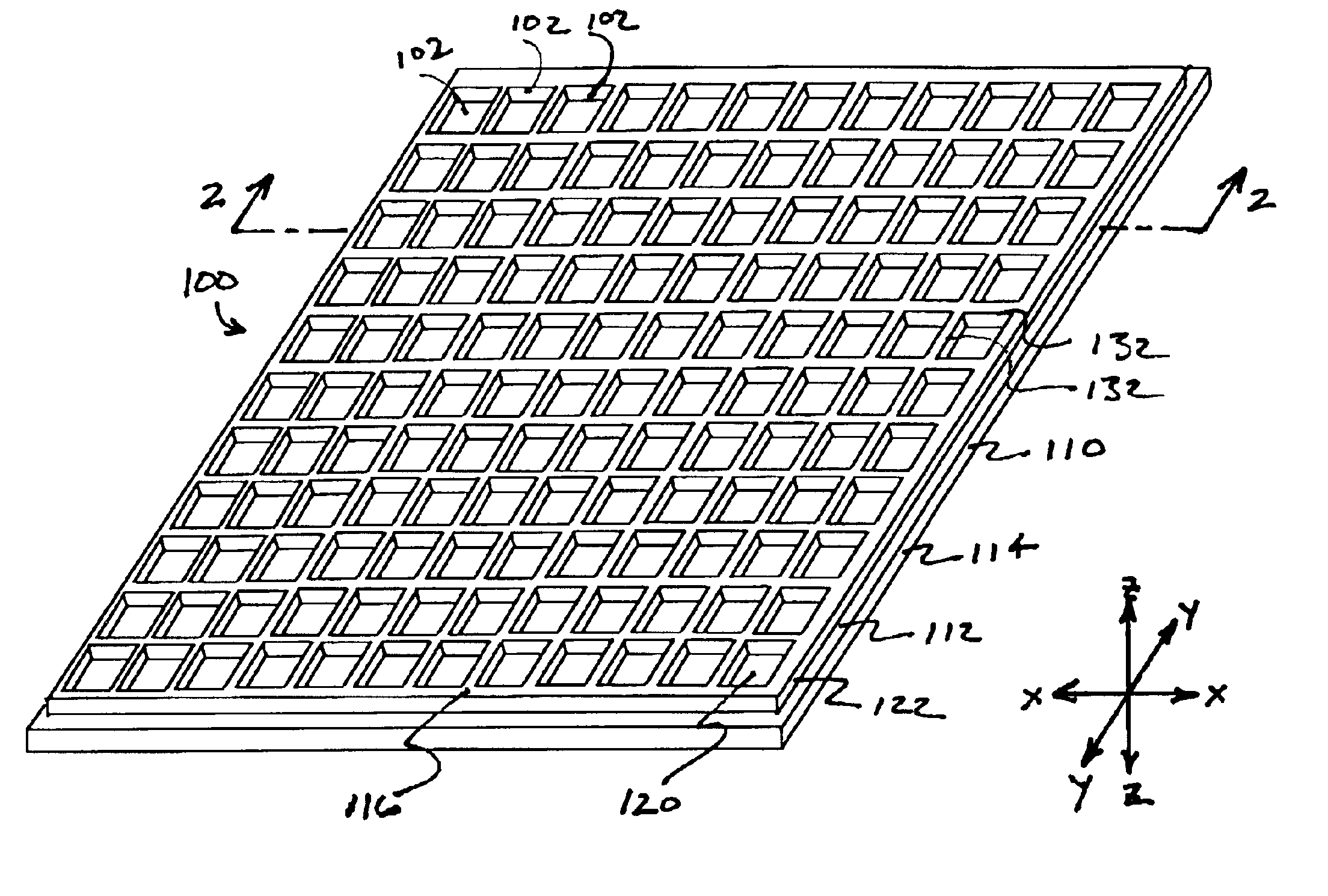
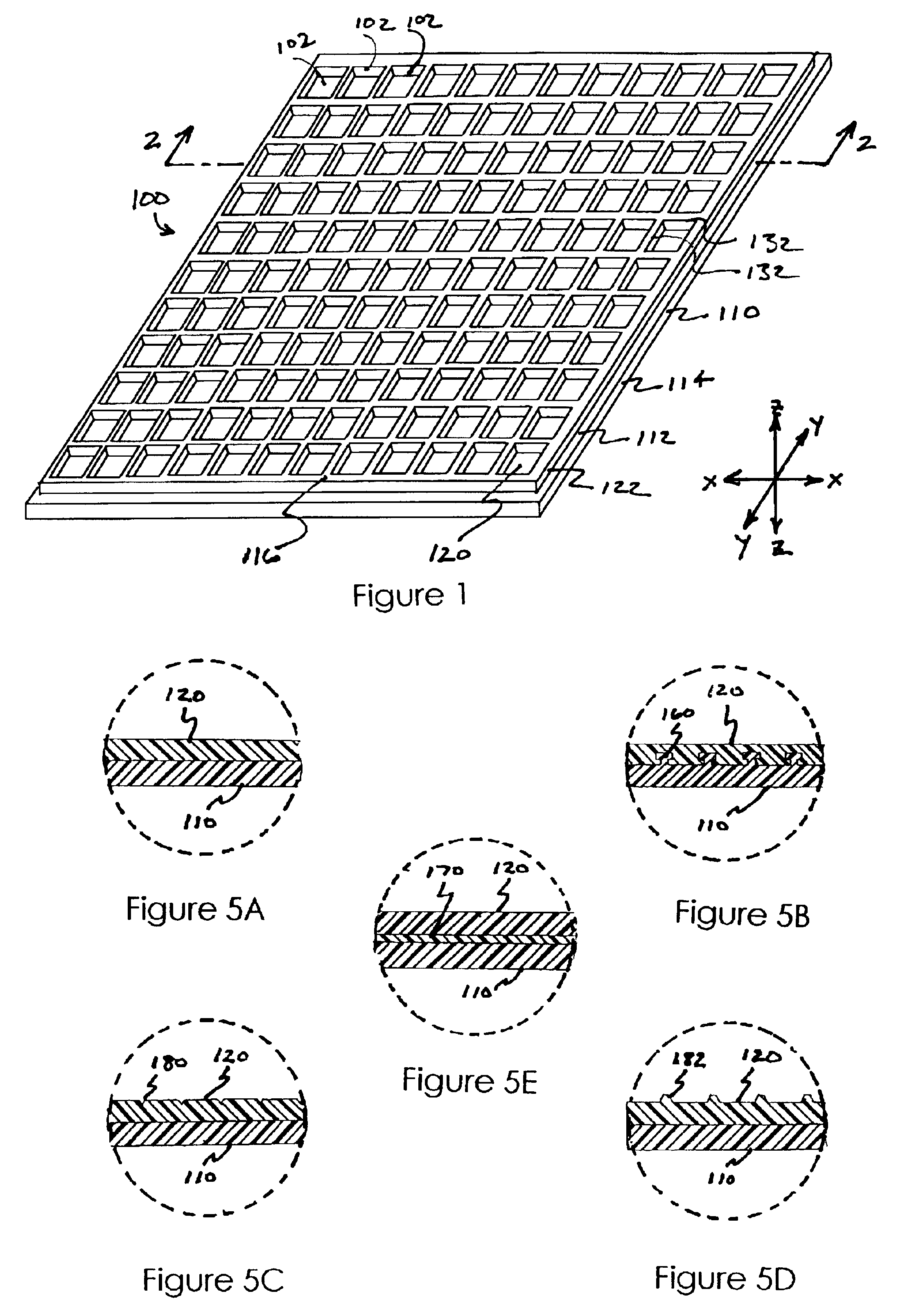
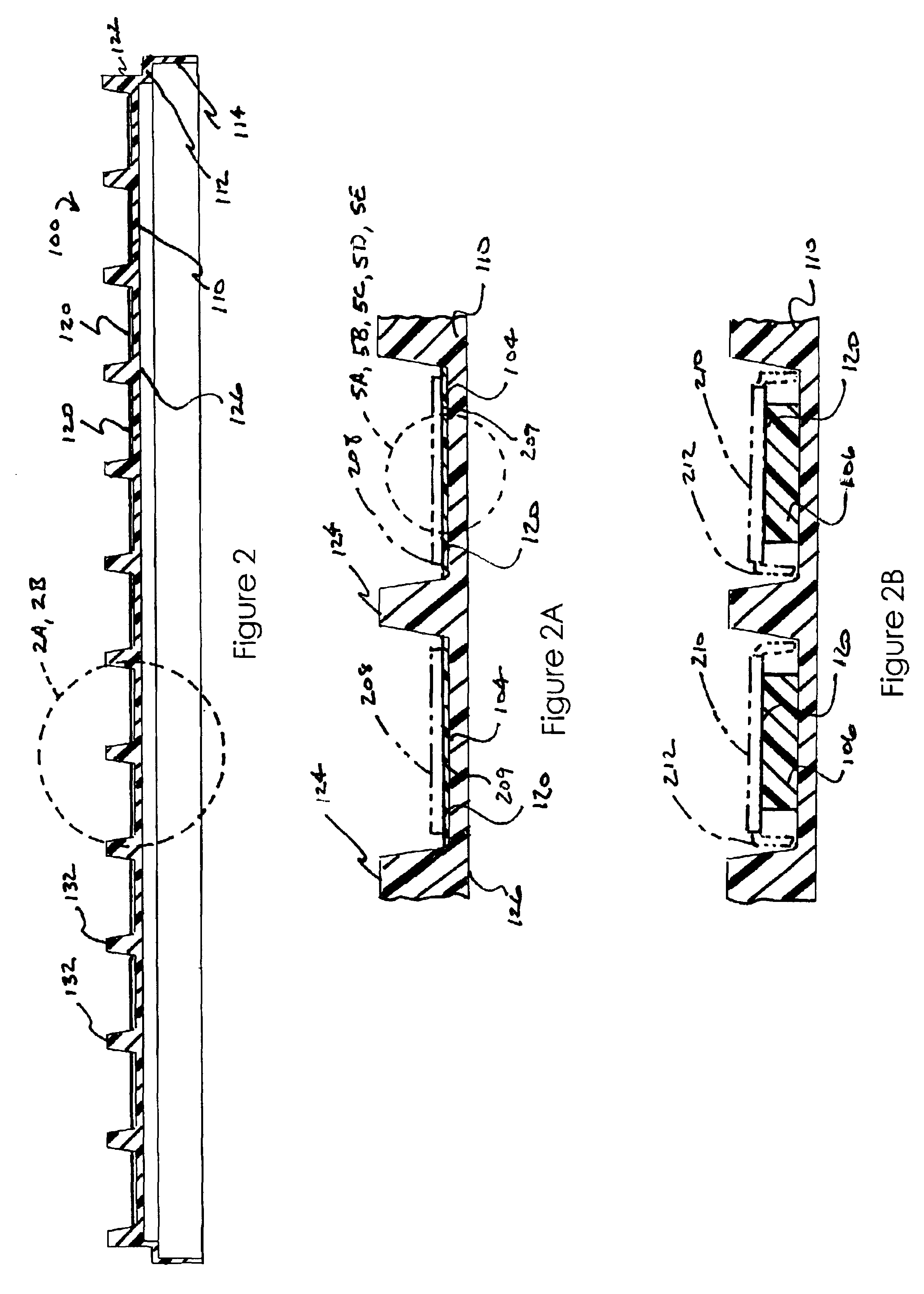
[0011]It is a feature and advantage of the invention that the matrix tray has improved means of retaining components in the pockets or other structures, in that the components are retained only by adhesion between a flat surface of the component with a thermoplastic elastomer contact surface of the tray.
[0012]It is another feature and advantage of the invention that components are retained in place on the tray with sufficient force so that the tray can be inverted and can be subjected to normal shipping and handling shocks without the components being dislodged.
[0013]It is another feature and advantage of the invention that no lateral or vertical physical restraining structures are used to retain components in place on the tray, apart from the thermoplastic elastomer contact surface.
[0014]It is another feature and advantage of the invention that no separate adhesive substance is used on the contact layer surface to adhere the components to the contact surface, thereby reducing the amount of process contamination from solvents and other undesirable chemicals.
[0015]It is another feature and advantage of the invention that the tray contact surface and body portion may be ESD safe for the components retained.
[0016]It is another feature and advantage of the invention that the tray is more easily recyclable than known matrix trays.

Problems solved by technology

The devices are sensitive to physical and electrical damage, and must be handled carefully when being transported between processing steps.
A problem with previous trays using typical adhesive materials is that such adhesives may attract contaminants in the form of particles that can damage the devices.
These contaminants can be difficult to remove from the tray by washing without causing degradation of the adhesive.
In addition, the adhesive itself may contain solvents or other undesirable chemicals that can contaminate the devices or the process.
Also, the adhesive itself may undergo changes in response to environmental conditions, becoming either too tacky so as to interfere with the operation of the robotic device handling process, or not tacky enough so as not to properly secure the devices in place.
Prior art matrix trays having pockets or other physical structures to retain the device may also present problems.
Devices such as bare or leadless chips are not easily captured in a physical structure due to the lack of projections on the device.
Also, the devices may become dislodged from the physical restraints during handling, leading to device damage or improper positioning for handling by a robot.

Method used


Image

  • Matrix tray with tacky surfaces
  • Matrix tray with tacky surfaces
  • Matrix tray with tacky surfaces

Examples


Embodiment Construction

[0032]The accompanying Figures depict embodiments of the matrix tray of the present invention, and features and components thereof. Any references to front and back, right and left, top and bottom, upper and lower, and horizontal and vertical are intended for convenience of description, not to limit the present invention or its components to any one positional or special orientation. Any dimensions specified in the attached Figures and this specification may vary with a potential design and the intended use of an embodiment of the invention without departing from the scope of the invention.

[0033]As used herein, the term “about” means that dimensions, sizes, tolerances, formulations, parameters, shapes and other quantities and characteristics are not and need not be exact, but may be approximate and / or larger or smaller, as desired, reflecting tolerances, conversion factors, rounding off, measurement error and the like, and other factors known to those of skill in the art. In general...


PUM

PropertyMeasurementUnit
surface energyaaaaaaaaaa

Abstract

A tray for handling and retaining a plurality of small components comprising a rigid body portion with a plurality of pockets formed therein. Each of the pockets has an elastomeric contact surface for contacting and retaining a component. The contact surface may be formed from a thermoplastic material having a surface energy between 20 dyne / cm and 100 dyne / cm, and a surface electrical resistivity of between about 1×10⁴ ohms / square and 1×10¹² ohms / square. The material for the contact portion may be urethane, polybutylene terephthalate, polyolefin, polyethylene terephthalate, styrenic block co-polymer, styrene-butadiene rubber, polyether block polyamide, or polypropylene / crosslinked EDPM rubber. The body portion may be formed from acrylonitrile-butadiene-styrene, polycarbonate, urethane, polyphenylene sulfide, polystyrene, polymethyl methacrylate, polyetherketone, polyetheretherketone, polyetherketoneketone, polyether imide, polysulfone, styrene acrylonitrile, polyethylene, polypropylene, fluoropolymer, polyolefin, or nylon. The body portion may have a peripheral border region and a downwardly projecting skirt portion to facilitate stacking of multiple trays.

Description

FIELD OF THE INVENTION[0001]This invention relates to trays for handling device, more particularly it relates to trays for handling semiconductor devices.BACKGROUND OF THE INVENTION[0002]Processing of semi-conductor devices involves many processing steps. The devices are sensitive to physical and electrical damage, and must be handled carefully when being transported between processing steps. In addition, robots are often used to handle the devices during processing. These robots require precise positioning of the device to allow the robot to efficiently locate and engage the device. As a result, specialized trays have been developed to facilitate transport of the devices between processing steps.[0003]One type of previous chip tray, known as a film frame, generally has a frame portion surrounding a thin film. On the top surface of the thin film, a layer of adhesive is disposed. A plurality of devices may then be arranged at any desired locations on the adhesive, and the adhesive se...

Claims


Application Information

Patent Timeline
Patent Type & Authority Patents(United States)
IPC IPC(8): B32B25/00B32B25/08H01L21/67H01L21/673
CPCB32B25/08H01L21/673Y10T428/1352Y10S414/14Y10T428/13H01L2221/68313
Inventor EXTRAND, CHARLES W.MANGANIELLO, FRANK
Owner ENTEGRIS INC
Learn More