Active turbine tip clearance control system

a technology of tip clearance control and gas turbine engine, which is applied in the direction of motors, leakage prevention, mechanical equipment, etc., can solve the problems of affecting the operation and/or efficiency of the atcc system, and achieve the effect of increasing the pressure differential over the atcc system and selecting the energy level of the cooling air flow passing

Active Publication Date: 2013-06-20
PRATT & WHITNEY CANADA CORP
View PDF6 Cites 37 Cited by
  • Summary
  • Abstract
  • Description
  • Claims
  • Application Information

AI Technical Summary

Benefits of technology

[0006]In a further aspect, there is provided a method for actuating an active tip clearance control (ATCC) system of a gas turbine engine, comprising amplifying a control signal for actuating the ATCC system in steps of: a) selectively actuating a solenoid valve using an electric signal as the control signal to control an on / off condition of a high pressure air flow; and b) using the on / off-controlled high pressure air flow to selectively actuate an ejector which drives a cooling air flow through the ATCC system, thereby selectively increasing an energy level of the cooling air flow passing through the ATCC system, resulting in an increased pressure differential over the ATCC system.

Problems solved by technology

For engines in which this pressure differential is very low, the operation and / or efficiency of the ATCC system may be at risk.

Method used


Image

  • Active turbine tip clearance control system
  • Active turbine tip clearance control system
  • Active turbine tip clearance control system

Examples


Embodiment Construction

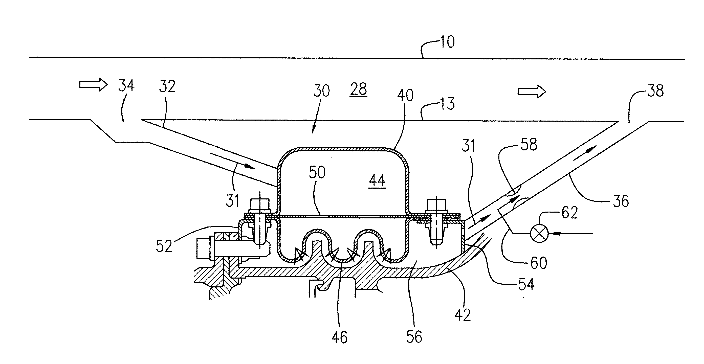
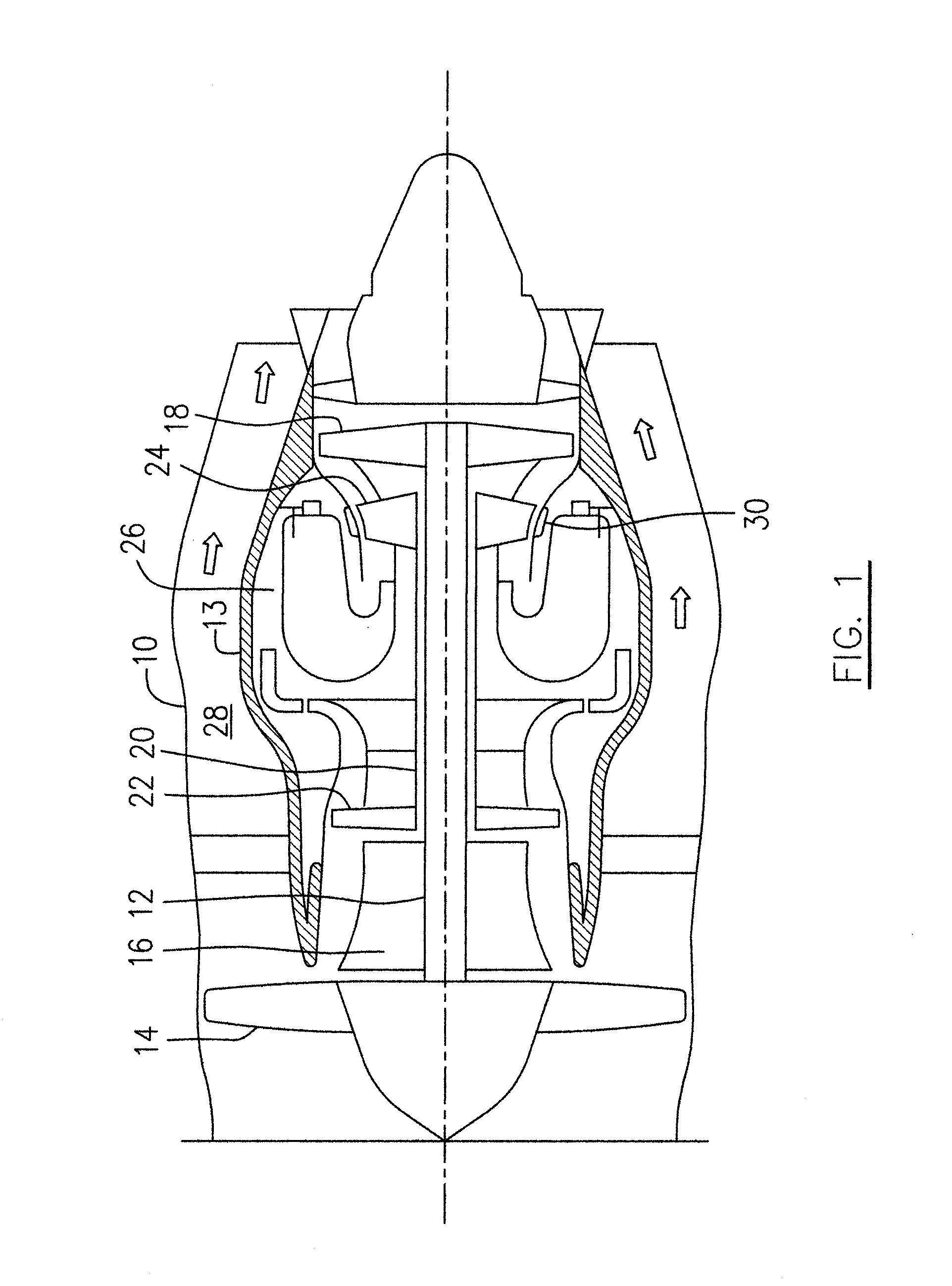
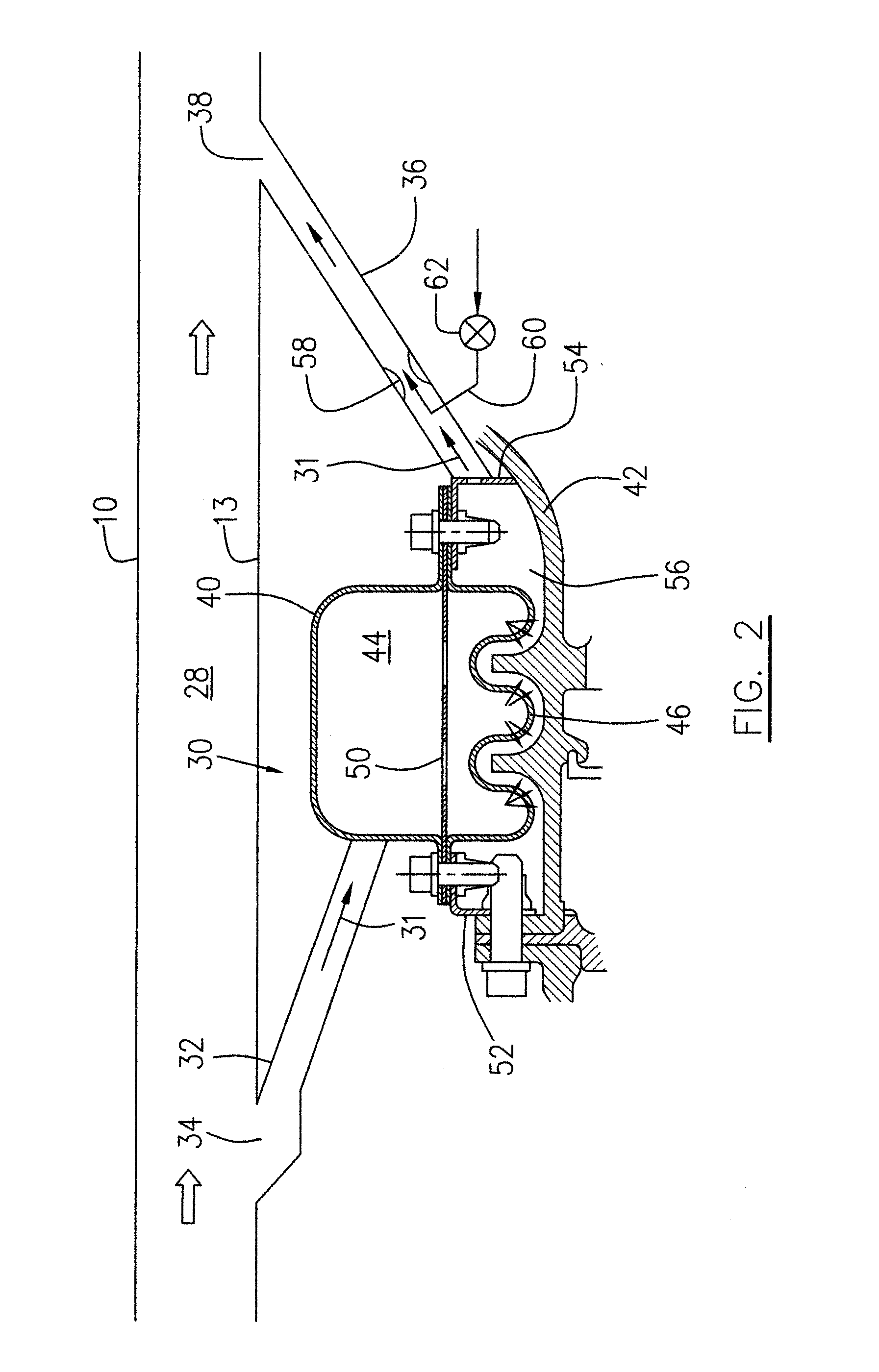
[0014]FIG. 1 illustrates a turbofan gas turbine aircraft engine presented as an example of the application of the described concept, including a housing or nacelle annular outer case 10, an annular core case 13, a low pressure spool assembly seen generally at 12 which includes a fan assembly 14, a low pressure compressor assembly 16 and a low pressure turbine assembly 18, and a high pressure spool assembly seen generally at 20 which includes a high pressure compressor assembly 22 and a high pressure turbine assembly 24. The annular core case 13 surrounds the low and high pressure spool assemblies 12 and 20 in order to define a main fluid path (not numbered) therethrough. In the main fluid path there is provided a combustor to constitute a gas generator section 26. An annular bypass air duct 28 is defined radially between the annular outer case 10 and the annular core case 13 for directing a main bypass air flow (not numbered) driven by the fan assembly 14, to pass therethrough and t...


PUM


Abstract

An active tip clearance control (ATCC) system of a gas turbine engine includes an ejector to selectively drive an air flow passing through the ATCC system. A high pressure air flow as a motive flow of the ejector is controlled by a valve according to engine operation requirements.

Description

TECHNICAL FIELD[0001]The described subject matter relates generally to a gas turbine engine and more particularly, to an active tip clearance control (ATCC) system of a gas turbine engine.BACKGROUND OF THE ART[0002]Conventional active tip clearance control (ATCC) systems in a turbofan gas turbine engine use the fan driven bypass air, a portion of which is directed through a diffusion duct to the high pressure turbine case manifold. This portion of bypass air is directed to flow over the high pressure turbine case through a series of impingement holes. A modulating valve may be incorporated between an air inlet and the diffusion duct. This valve adjusts the portion of bypass air flow according to the engine requirements such that the appropriate tip clearance between the turbine blades and the turbine shroud is maintained. Conventional ATCC systems rely on the pressure differential between an inlet scoop at the bypass duct and a downstream location of the bypass duct where the vent c...

Claims


Application Information

Patent Timeline
Patent Type & Authority Applications(United States)
IPC IPC(8): F01D17/00F01D5/02
CPCF01D11/20F01D11/24F01D11/22
Inventor ELEFTHERIOU, ANDREASALECU, DANIEL
Owner PRATT & WHITNEY CANADA CORP
Why Eureka
Try Eureka