
Airfoil Design for Wakeless Wind Turbine Tower Structures

Inactive Publication Date: 2013-06-20
CLIPPER WINDPOWER INC
View PDF4 Cites 5 Cited by
  • Summary
  • Abstract
  • Description
  • Claims
  • Application Information

AI Technical Summary

Benefits of technology

This patent describes a new wind turbine design that has certain technical advantages. The turbine has a tower with at least one blade that is rotatably mounted to a nacelle. The nacelle is mounted to the tower in stationary relationship. The tower has a unique shape that helps to improve the air turbine's performance. The tower can be made in a single piece or in two parts. The twin design has two separate airfoils that are symmetrically arranged and face each other. This design helps to create a more efficient wind turbine that can capture more wind energy.

Problems solved by technology

First, circular cross section towers must be designed to react with the turbine's aerodynamic forces in any direction. Since the aerodynamic forces are predominantly along the wind direction, the symmetric design is non-ideal from a material usage standpoint. This use of extra material—typically steel—drives up the cost of the wind turbine.
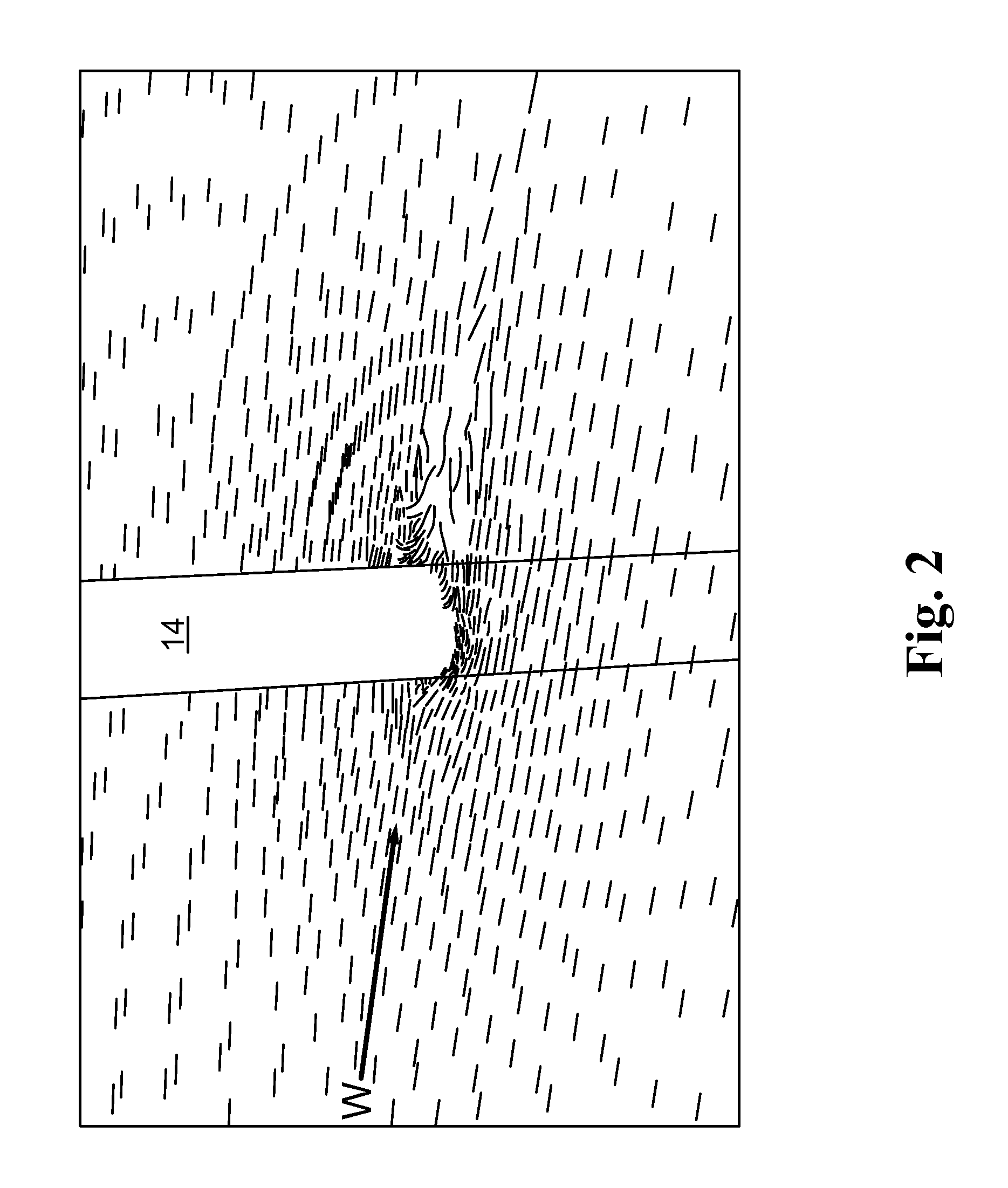
Second, circular cross section towers create a pronounced “tower shadow effect.” The tower shadow effect refers to the aerodynamic wake that is present immediately downwind of the tower. In this aerodynamic wake zone, the wind velocity is dramatically reduced compared to the free stream (unencumbered) velocity. The tower shadow effect prohibits the use of a downwind turbine (one in which the blades are downwind of the tower), since the tower shadow effect momentarily unloads each blade as it passes through the aerodynamic wake zone. This momentary unloading of the aerodynamic force causes a loud audible noise to be generated. The noise is proportional to the magnitude of the tower shadow. In addition to the audible noise, the tower shadow effect also causes periodic force perturbations to impact the wind turbine system.
Another drawback to upwind turbines is that the blades must be rigid enough to ensure that they will not bend and strike the tower when subjected to high wind loads.
Stiffer blades require more material to make, thereby increasing the cost of the wind turbine.
Engineers have designed wind turbines in which the blades are set at a pitch (slight angle) off the vertical so that the distance between the blades and the tower is greatest when the blades are at their lowest point, but this solution has the disadvantage of reducing the wind driving force, and thus, electrical output.

Method used


Image

  • Airfoil Design for Wakeless Wind Turbine Tower Structures
  • Airfoil Design for Wakeless Wind Turbine Tower Structures
  • Airfoil Design for Wakeless Wind Turbine Tower Structures

Examples


first embodiment

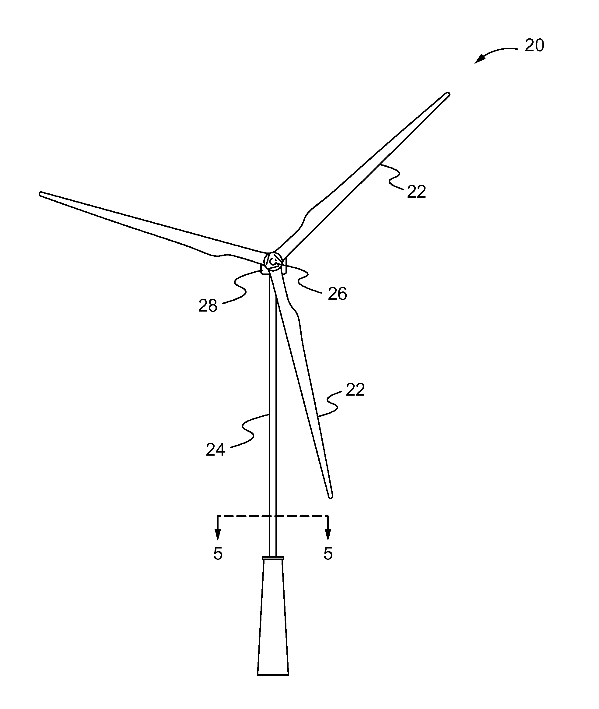
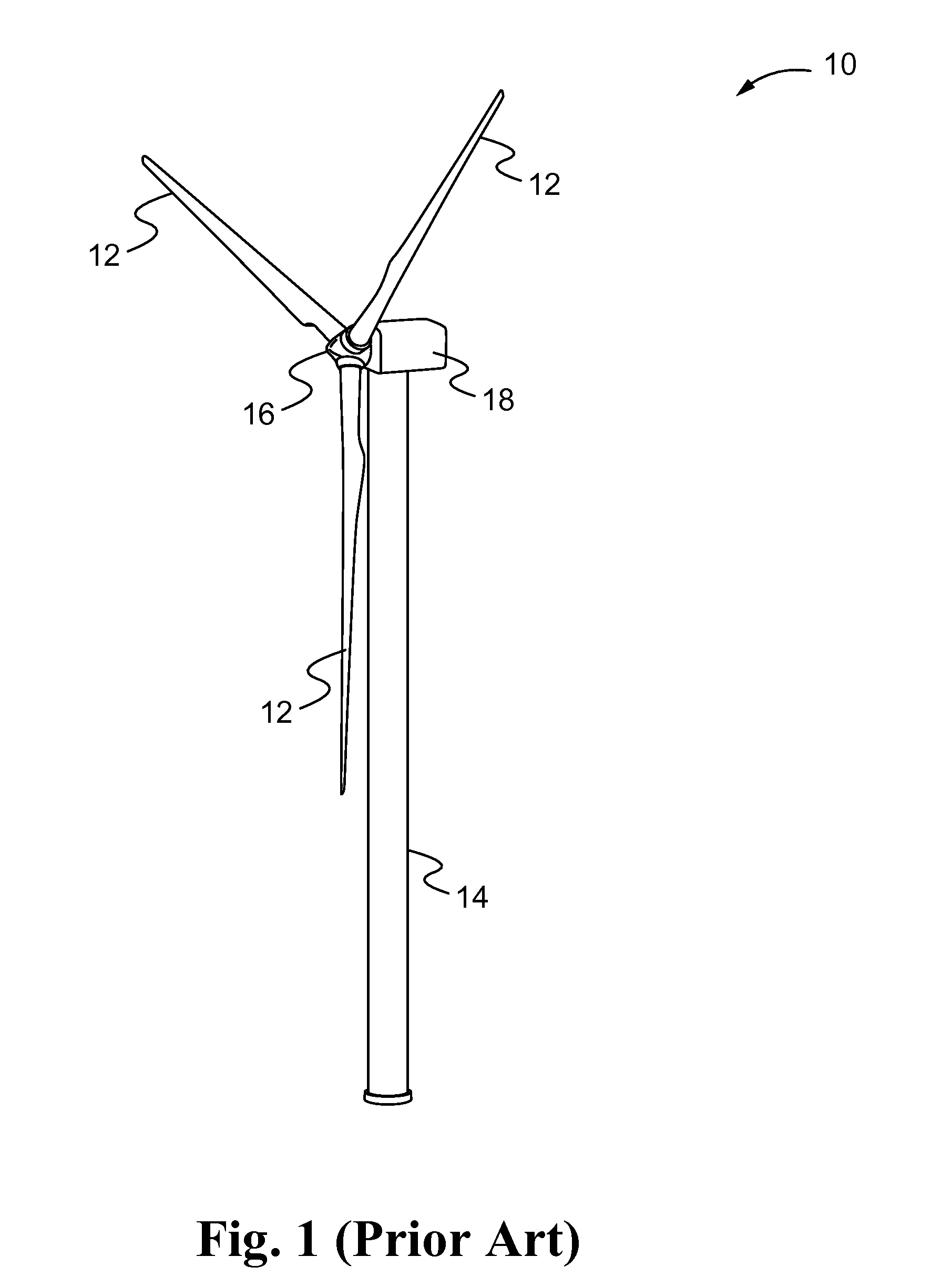
[0035]FIGS. 3 and 4 are front and side views of a wind turbine 20 made according to the present invention. Like the conventional wind turbine 10, this new wind turbine 20 comprises blades 22 connected to a hub 26, which in turn is connected to a nacelle 28, all of which is mounted atop a tower 24. However, in contrast to the conventional wind turbine 10, the tower 24 is an asymmetric, yawing (rotating) tower 24 that results in a substantially reduced tower shadow effect.

[0036]FIG. 5 is a cross sectional view of the wind turbine tower 24 of FIG. 4 taken along line 5-5. As shown in this cross sectional view, the tower 24 comprises left and right side walls 32, 34 connected along a vertical leading edge 36 and a vertical trailing edge 38 to form a substantially hollow shell. The left and right side walls 32, 34 are curved yet symmetrical about a major chord (A) and, therefore, form a symmetric airfoil. A minor (shorter) chord (B) is defined by a line running perpendicular to the major ...

second embodiment

[0039]A second embodiment of the invention will now be described that also utilizes a full tower yawing system like the first embodiment. As shown in FIGS. 7 and 8, this second embodiment of a wind turbine 50 comprises blades 52 connected to a hub 56, which in turn is connected to a nacelle 58, all of which is mounted atop a tower 54.

[0040]FIG. 9 is a cross sectional view of the wind turbine tower 54 of FIG. 7 taken along line 9-9. The tower 54 comprises two separate vertical supports or airfoils 62, 62′ that together form a nozzle 64 which delivers a relatively high speed jet of air to fill the aerodynamic wake zone created behind the tower 54.

[0041]Each airfoil 62, 62′ comprises an outer wall 66, 66′ and an inner wall 68, 68′ connected at a leading edge 70, 70′ and at a trailing edge 72, 72′ to form a substantially hollow shell. In contrast to the first embodiment, each airfoil 62, 62′ is asymmetrical about its major chord (C, C′), with one wall, the outer wall 62, 62′, being subs...


PUM


Abstract

A novel wind turbine is provided that reduces or eliminates aerodynamic wake downwind of the tower to allow for the wind turbine to face away from the direction of the wind. The wind turbine comprises a tower and a rotor rotatably mounted to a nacelle which is mounted to the tower in stationary relationship therewith. The tower has a yaw bearing at its base so that it is rotatable about a vertical axis. In one embodiment the tower comprises a single airfoil symmetric about its major chord. In another embodiment the tower comprises a pair of spaced apart asymmetric airfoils defining a nozzle-like space there between through which a relatively high speed jet of air can travel to fill the aerodynamic wake zone behind the tower.

Description

FIELD OF THE DISCLOSURE[0001]The present disclosure relates generally to wind turbines and, more particularly, to an improved design for wind turbine towers that reduces or eliminates aerodynamic wake downwind of the tower.BACKGROUND OF THE DISCLOSURE[0002]A conventional wind turbine typically includes a set of two or three large blades mounted to a hub. The blades and the hub together are referred to as the rotor. Wind causes the rotor to rotate about a horizontal main shaft, which in turn is operatively connected via a speed increasing gear box to a generator or a set of generators that produce electric power. The main shaft, the gear box and the generator(s) are all situated within a nacelle, which is situated on top of a tower.[0003]In recent years, engineers have designed wind turbines of all sizes and integrated them with electric power generation systems to create electricity to support the needs of both industrial and residential applications. As the wind power market has ma...

Claims


Application Information

Patent Timeline
IPC IPC(8): F03D11/04
CPCY02E10/726Y02E10/728F05B2240/912F05B2240/2213F03D11/04F03D13/20Y02E10/72F03D80/70
Inventor HIMMELMANN, RICHARD
Owner CLIPPER WINDPOWER INC
Learn More