
Electronic unit mounting

a technology for electronic units and mounting brackets, applied in the field of electronic units, can solve the problems of increasing the weight and complexity of electrical harnesses, affecting the safety of the engine, so as to reduce the number of anti-vibration mounts that are required to assemble the engine, and prolong the life of the electrical raft. the effect of the electrical raft and the reduction of the total number of mounting brackets

Active Publication Date: 2013-06-27
ROLLS ROYCE PLC
View PDF14 Cites 14 Cited by
  • Summary
  • Abstract
  • Description
  • Claims
  • Application Information

AI Technical Summary

Benefits of technology

The patent describes an arrangement / method where the engine's electronic control unit (ECU) can be easily accessed without needing dedicated access panels. This helps speed up repair / maintenance procedures and reduces weight and drag on the engine, improving fuel efficiency. It also allows for better cooling of the ECU and reduces the need for dedicated cooling arrangements. Additionally, components that were conventionally mounted without anti-vibration mounts can now benefit from vibration isolation, improving their reliability and service life.

Problems solved by technology

This is typically a time consuming and relatively complex process.
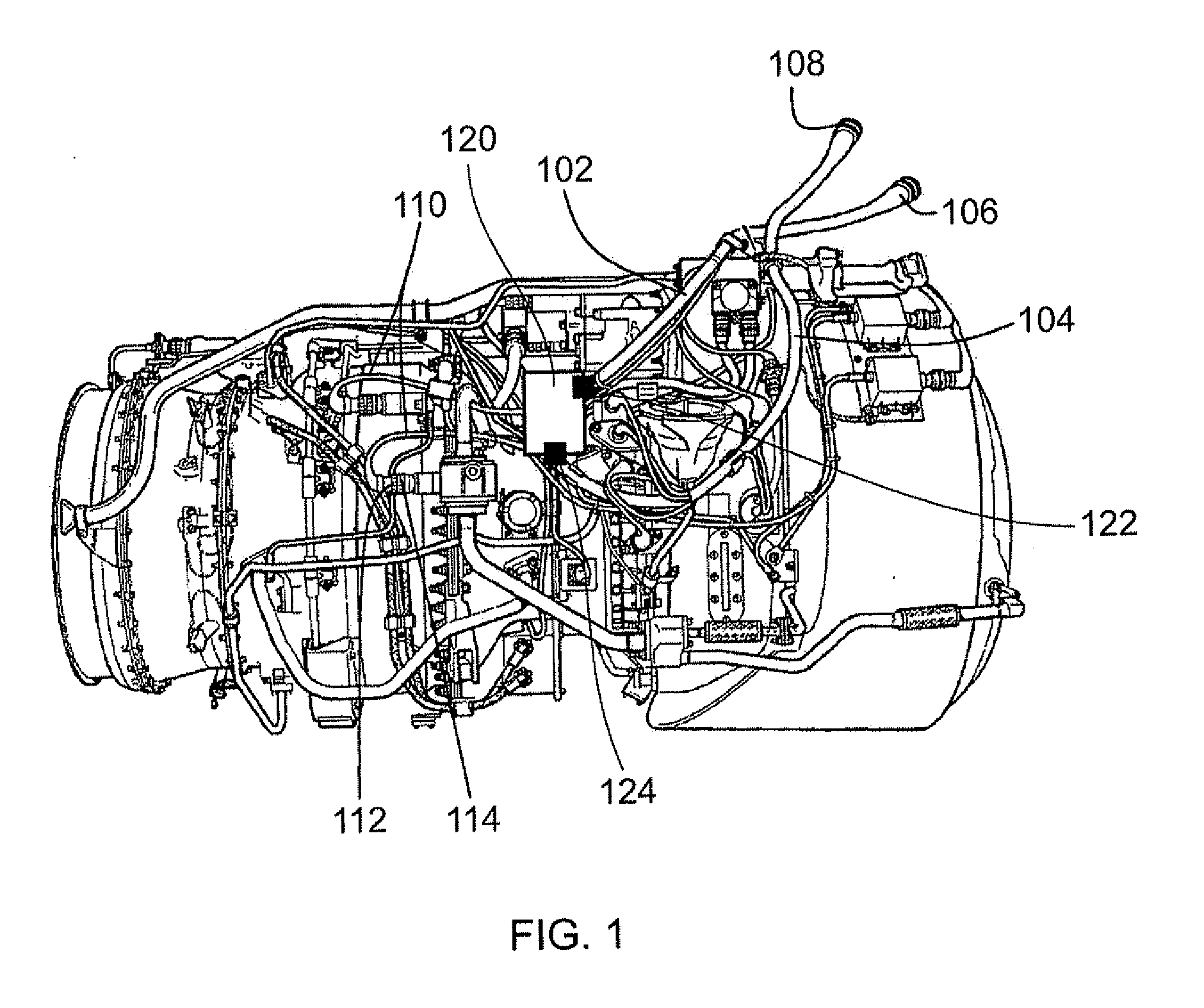
These conventional plug or socket connector components add weight and complexity to the electrical harnesses.
Thus, the conventional plug or socket connectors may be exposed to, for example, high temperatures and / or vibrations.
This means that the conventional exposed connectors are bulky and heavy.
Even such bulky and heavy connectors may still be susceptible to damage and / or becoming loose, for example due to engine vibration.
This makes the conventional harness 102, 104 itself bulky, heavy and difficult to manipulate.
The conventional harnesses occupy significant space within a gas turbine engine (for example within the nacelle of a gas turbine engine), and thus may compromise the design of the aircraft, for example the size and / or weight and / or shape of the nacelle.
This can make the assembly process complicated (and thus susceptible to errors) and / or time consuming.
Disassembly of the conventional harnesses (for example removal of the conventional harnesses from a gas turbine engine during maintenance and / or disconnection of the conventional harnesses from other components, such as the ECU) may also be complicated and / or time consuming.
Thus, in many maintenance (or repair or overhaul) procedures on a gas turbine engine, removal and subsequent refitting of the conventional electrical harness and / or connected ECU(s) may account for a very significant proportion of the operation time and / or account for a significant proportion of the potential assembly errors.
The electrical conductors in the conventional harnesses may be susceptible to mechanical damage.
For example, mechanical damage may occur during installation (for example through accidental piercing of the protective sleeves / braiding) and / or during service (for example due to vibration).
In order to reduce the likelihood of damage to the conductors in a conventional harness, the protective sleeves / braiding may need to be further reinforced, adding still further weight and reducing the ease with which they can be manipulated.
Similarly, the exposed electrical connectors used to connect one conductor to another conductor or conductors to electronic units, such as the ECUs, may be susceptible to damage and / or may add significant weight to the engine.
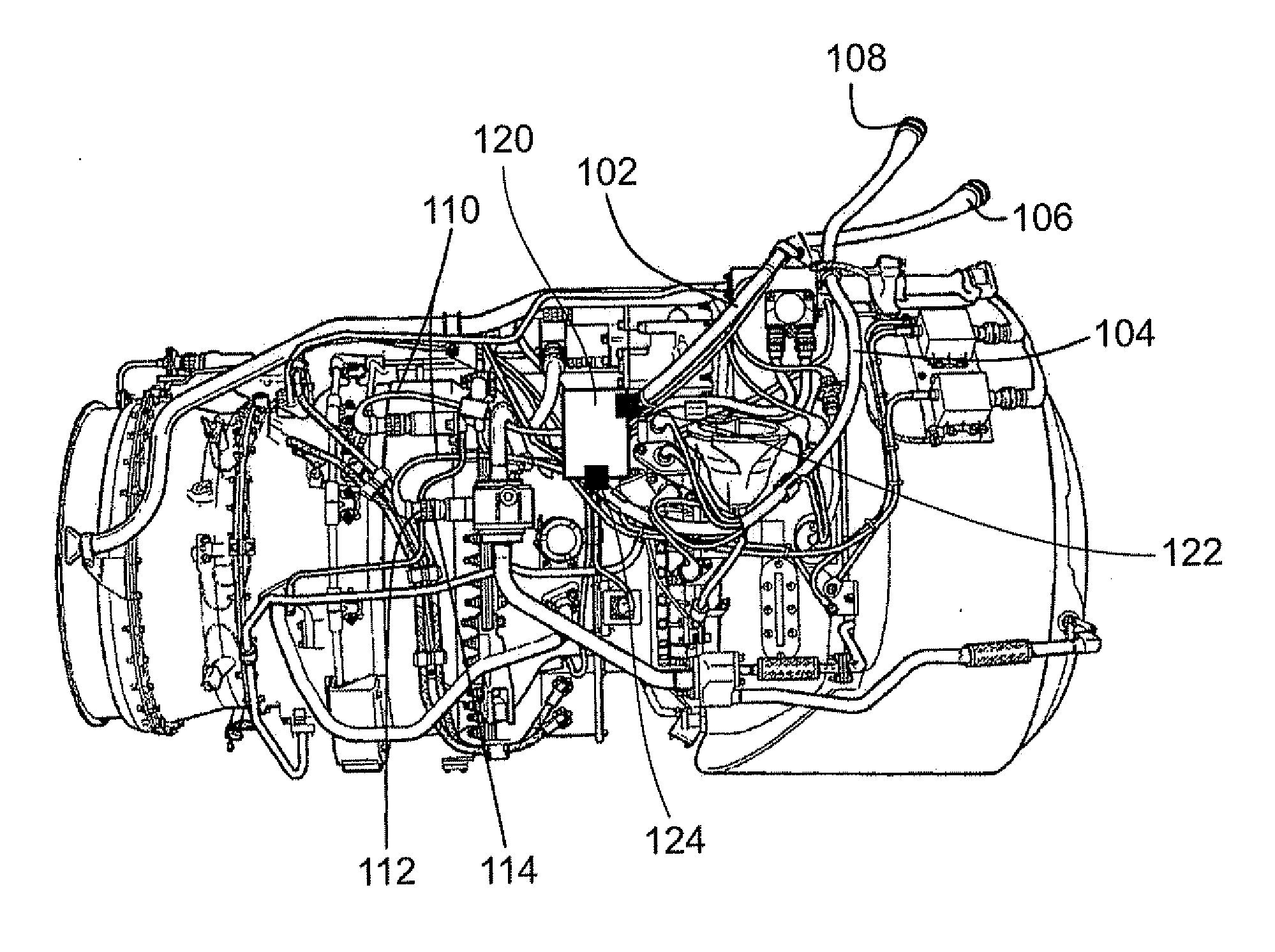
Thus, once assembled, ECUs in a conventional arrangement are hidden and inaccessible from the outside of the assembled engine.
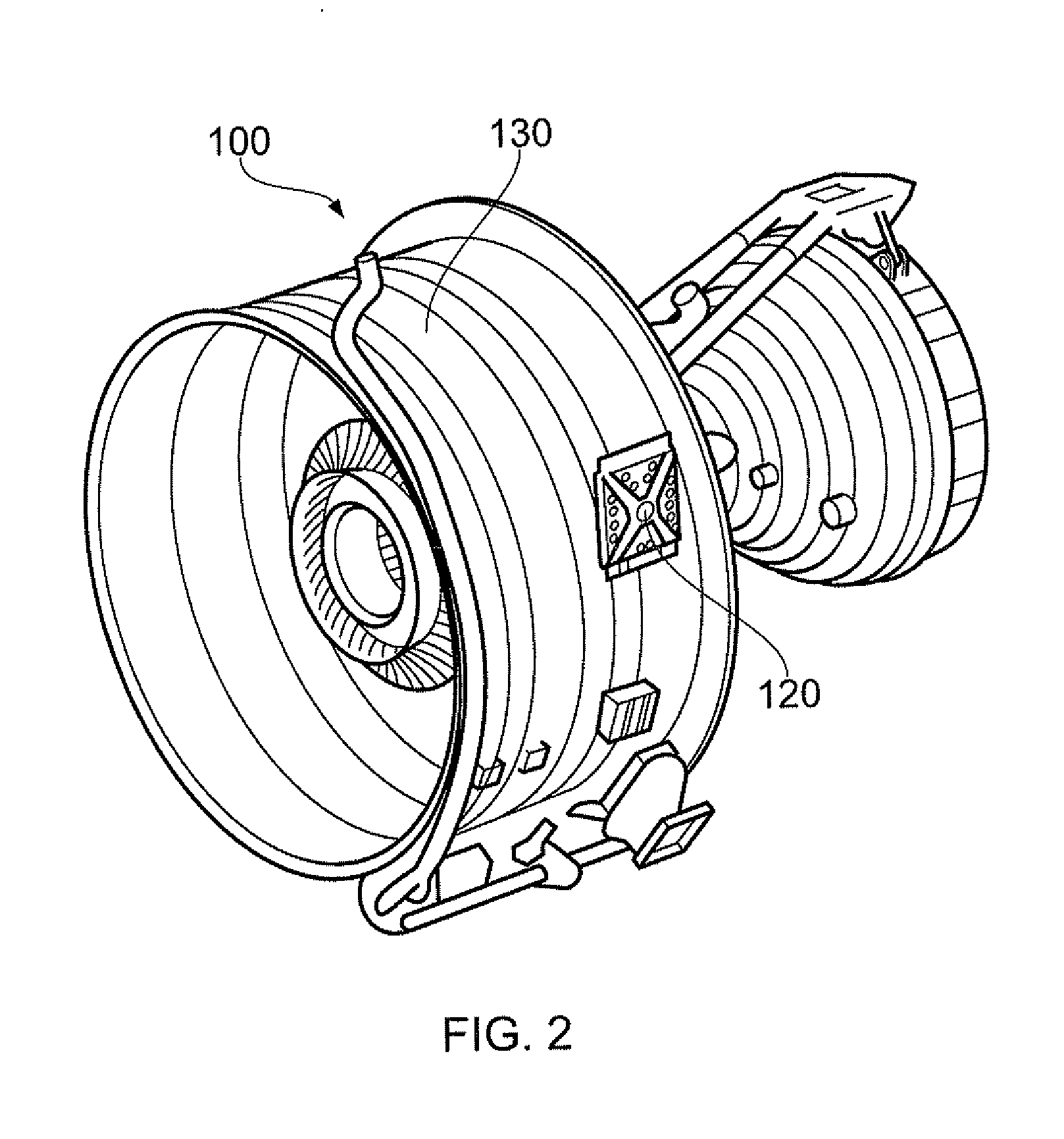
However, during assembly, the ECU 120 is manually connected to various flexible electrical wires and / or harnesses, and mechanically mounted to the fan case 130, in a time-consuming and relatively complex procedure.
Opening the panels is a time consuming process, especially for larger engines in which a machine is required to lift and / or support the large, heavy panels.
Furthermore, even when the doors are opened, the access to the ECU and related parts is usually limited and thus performing any maintenance / repair tasks can be difficult and / or time consuming.
The cramped working environment, as well as the possibility of the moveable (hinged) panels becoming dislodged, means that there is a significant risk of injury to maintenance personnel.
This requirement drives significant weight into the structure, which in turn has an impact on overall fuel consumption of an aircraft to which the engine may be attached.

Method used


Image

  • Electronic unit mounting
  • Electronic unit mounting
  • Electronic unit mounting

Examples


Embodiment Construction

[0070]With reference to FIG. 3, a ducted fan gas turbine engine (which may be referred to as a turbofan engine) generally indicated at 10 has a principal and rotational axis X-X. The engine 10 comprises, in axial flow series, an air intake 11, a propulsive fan 12, an intermediate pressure compressor 13, a high-pressure compressor 14, combustion equipment 15, a high-pressure turbine 16, and intermediate pressure turbine 17, a low-pressure turbine 18 and a core engine exhaust nozzle 19. The engine also has a bypass duct 22 and a bypass exhaust nozzle 23. The example turbofan engine 10 shown in FIG. 3 has a fan case 24 and a nacelle 30. The nacelle 30 at least partially surrounds the fan case 25. The nacelle 30 has an outer surface (or skin) 32.

[0071]The gas turbine engine 10 works in a conventional manner so that air entering the intake 11 is accelerated by the fan 12 to produce two air flows: a first air flow A into the intermediate pressure compressor 13 and a second air flow B whic...


PUM

PropertyMeasurementUnit
drag coefficientaaaaaaaaaa
electrical assemblyaaaaaaaaaa
flexibleaaaaaaaaaa

Abstract

An electrical assembly 600 comprising an electrical raft 200 and an electronic unit 300 is provided to a gas turbine engine 10. The electrical raft 200 has electrical conductors 252 embedded in a rigid material 220, which may be a rigid composite material. The electrical conductors 252 are in electrical contact with the electronic unit 300. When the electronic unit 300 is installed, at least a part 310 of it forms a part of a gas-washed surface of the engine 10. The electronic unit 300 is then easily accessible from the engine 10, and potentially complex and / or heavy access doors / panels may not be required.

Description

CROSS-REFERENCE TO RELATED APPLICATIONS[0001]This application is based upon and claims the benefit of priority from British Patent Application Number 1122140.5 filed 22 Dec. 2011, British Patent Application Number 1122143.9 filed 22 Dec. 2011, British Patent Application Number 1203991.3 filed 7 Mar. 2012 and British Patent Application Number 1207733.5 filed 3 May 2012, the entire contents of which are incorporated by reference.BACKGROUND OF THE INVENTION[0002]1. Field of the Invention[0003]This invention relates to an electronic unit mounted to an engine. In particular, the invention relates to mounting an electronic unit to a gas turbine engine in such a way that that it forms part of the surface of the engine.[0004]2. Description of the Related Art[0005]A typical gas turbine engine may be provided with one or more electronic units, which may be referred to as electronic control units (ECUs), which may have the function of controlling and / or facilitating processes performed by the ...

Claims


Application Information

Patent Timeline
Patent Type & Authority Applications(United States)
IPC IPC(8): F02C7/20
CPCF02C7/12Y10T29/49236B23P6/005H02G1/00H02G3/02H02G3/04H01R12/00F02C7/00F02C7/32Y02T50/672F24H1/105H05B1/0236H05B3/28F02C7/047F02C7/224Y10T29/49117Y10T156/10Y10T29/49234Y10T29/49238Y10T29/49002F02C7/20H02G3/0487H05K1/0393F05D2300/603H05K2201/029F05D2260/30Y02T50/60F01D25/28F02C7/22F02C7/222H05K9/0098H02G3/32B60R16/0215B60R16/0207B64C3/34F02C7/141B60R16/08F02C7/16H01R12/57H01R12/592H01R12/515H01R12/51H01R12/61H01R12/59H02G3/00B60R16/00B60R16/02B64D29/08F16M13/02H05K7/20
Inventor BROUGHTON, PAULPEACE, RICHARDSKINNER, GARY ALANKENNEA, ROBIN CHARLES
Owner ROLLS ROYCE PLC
Learn More