Acoustic wave acquiring apparatus

a technology of acquiring apparatus and acoustic wave, which is applied in the direction of instruments, ultrasonic/sonic/infrasonic diagnostics, and specific gravity measurement. it can solve the problems of difficult comparison between an image before replacement and an image after replacement, the resolution and the imaging range cannot be changed during imaging, and the total imaging time increases

Inactive Publication Date: 2013-06-27
CANON KK
View PDF18 Cites 28 Cited by
  • Summary
  • Abstract
  • Description
  • Claims
  • Application Information

AI Technical Summary

Benefits of technology

[0028]According to the present invention, it is possible to provide a technique capable of changing resolution or an imaging area during imaging in an acoustic wave acquiring apparatus using a Fabry-Perot probe.

Problems solved by technology

That is, the resolution and the imaging range cannot be changed during imaging.
However, replacement of the probe causes increase in total imaging time.
Moreover, a position and shape of the object is changed during replacement, imaging in the same condition cannot be attained, and comparison between an image before replacement and an image after replacement is difficult.
Although imaging is performed by using a two-dimensional array photosensor in the Non Patent Literature 1, resolution or the imaging range cannot be changed in the aforementioned document because a lens or the like is not placed in the optical path of a measurement light irradiated from laser diode.

Method used


Image

  • Acoustic wave acquiring apparatus
  • Acoustic wave acquiring apparatus
  • Acoustic wave acquiring apparatus

Examples


first embodiment

[0042]The preferred embodiment of the present invention will be described with reference to figures.

[0043]A concept of measurement light in the present invention includes incident light incident upon a Fabry-Perot interferometer, and reflected light reflected by the Fabry-Perot interferometer to be led to an array photosensor. The measurement light is distinguished from excitation light irradiated to an object in order to generate an acoustic wave by utilizing a photoacoustic effect.

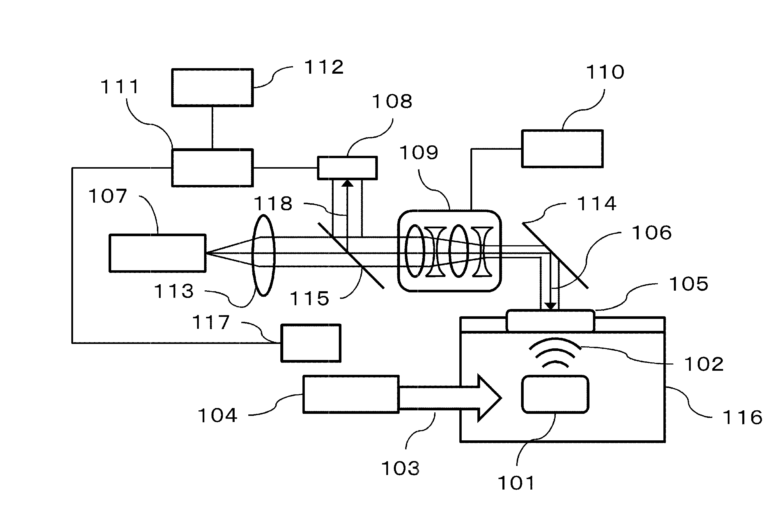
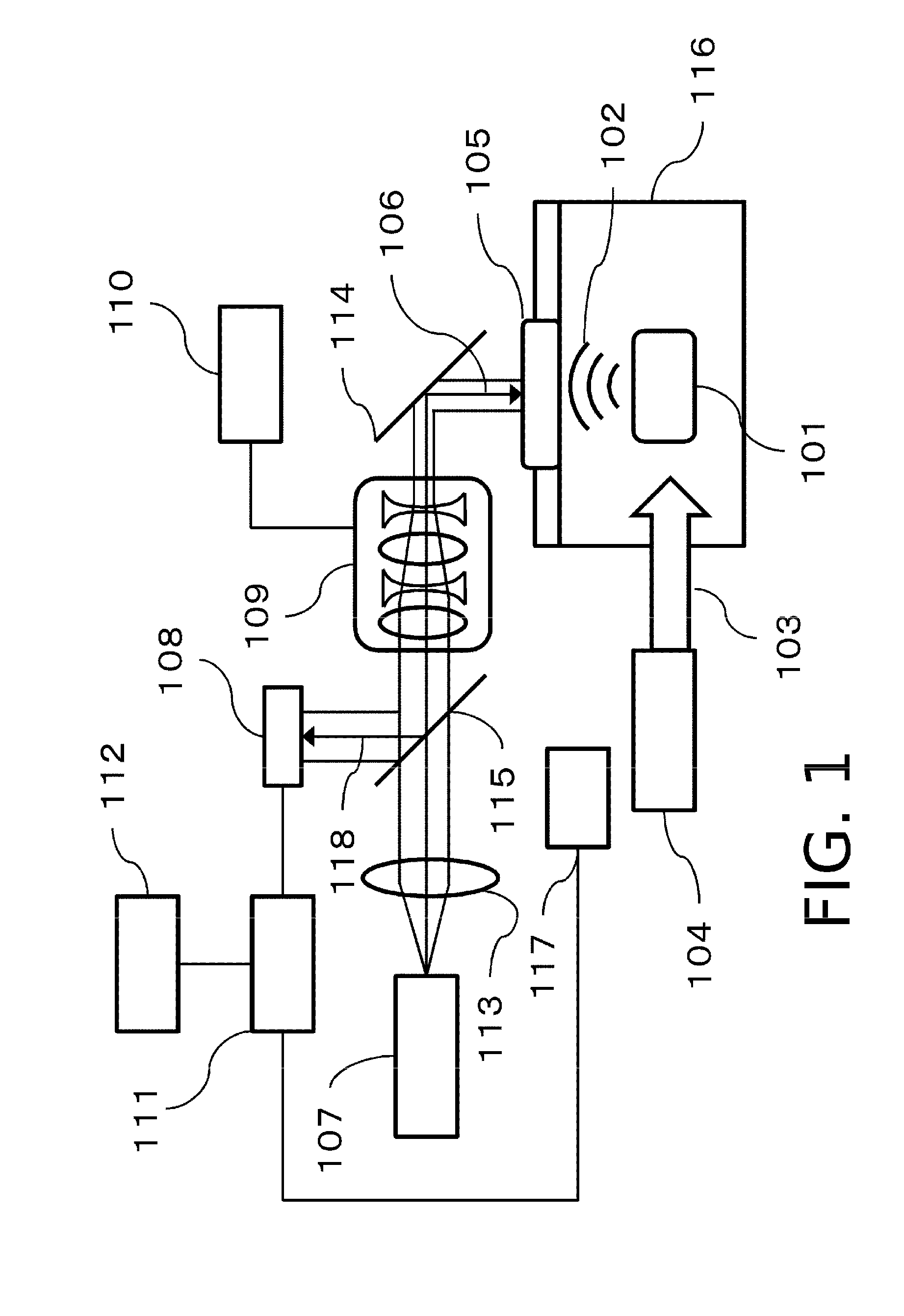
[0044]FIG. 1 is a figure illustrating a configuration example of an imaging apparatus according to the present embodiment.

[0045]The imaging apparatus according to the present embodiment includes an excitation light source 104. The excitation light source 104 irradiates an object 101 with excitation light 103. As a result, a light absorber inside or on a surface of the object 101 absorbs a part of light energy, so that a photoacoustic wave 102 generates. Examples of the light absorber inside the object in...

second embodiment

[0092]FIG. 4 is a figure illustrating a configuration example of an imaging apparatus according to the present embodiment.

[0093]In the imaging apparatus according to the present embodiment, a configuration of the apparatus and the like are similar to those of the first embodiment except a position where a zoom lens optical system 401 is arranged. That is, since a processor 411, a display unit 412, a controller 410, a mirror 414, a measurement light source 418, a lens 413, a PD 419, an excitation light source 416, and a water tank 421 have the same functions as those of the first embodiment, the detailed description thereof will not be repeated. Additionally, a point that excitation light 417 is irradiated to an object 415, and a photoacoustic wave 420 is generated and propagated is also similar to the first embodiment.

[0094]According to the present embodiment, the optical system 401 configured from the zoom lens optical system is located between a half mirror 402 and an array photos...

third embodiment

[0102]FIG. 5 is a figure illustrating a configuration example of an imaging apparatus according to the present embodiment.

[0103]In the imaging apparatus according to the present embodiment, a configuration of the apparatus and the like are similar to those of the first embodiment except a position where a zoom lens optical system 501 is arranged. That is, a processor 511, a display unit 512, a controller 510, a mirror 514, a measurement light source 518, a PD 519, an excitation light source 516, and a water tank 521 have the same functions as those of the first embodiment, the detailed description thereof will not be repeated. Additionally, a point that excitation light 517 is irradiated to an object 515, and a photoacoustic wave 520 is generated and propagated is also similar to the first embodiment.

[0104]According to the present embodiment, the optical system 501 configured from the zoom lens optical system is located between a half mirror 502 and a half mirror 503.

[0105]As a resu...


PUM

PropertyMeasurementUnit
wavelength rangeaaaaaaaaaa
diameteraaaaaaaaaa
reflectanceaaaaaaaaaa

Abstract

Provided is a technique capable of changing resolution or an imaging area during imaging, in an acoustic wave acquiring apparatus using a Fabry-Perot probe. An acoustic wave acquiring apparatus includes a measurement light source emitting measurement light, a probe having a Fabry-Perot interferometer including a first mirror, upon the side of which the measurement light is incident, and a second mirror, upon the side of which an elastic wave from an object is incident, an optical system changing a beam diameter of the measurement light, a controller controlling change in the beam diameter performed by the optical system, a photosensor measuring a light intensity of the measurement light reflected on the Fabry-Perot interferometer, and a processor acquiring intensity of the elastic wave on the basis of change in the light intensity measured by the photosensor due to incidence of the elastic wave.

Description

BACKGROUND OF THE INVENTION[0001]1. Field of the Invention[0002]The present invention relates to an acoustic wave acquiring apparatus.[0003]2. Description of the Related Art[0004]In general, imaging apparatuses using an X-ray, an ultrasound wave, and an MRI (nuclear magnetic resonance method) are often used in the mechanical field. On the other hand, a study of an optical imaging apparatus that obtains information in a biological body by propagating, inside an object such as an biological body, light irradiated from a light source such as a laser, and detecting the propagated light and the like has been also actively advanced in the mechanical field. A photoacoustic tomography (PAT) is proposed as one of such optical imaging techniques.[0005]The PAT is a technique of irradiating an object with pulsed light generated from a light source, detecting an acoustic wave generated from a biological tissue, which absorbs energy of light propagated and diffused in the object, on a plurality o...

Claims


Application Information

Patent Timeline
Patent Type & Authority Applications(United States)
IPC IPC(8): G01H9/00G01N21/55
CPCG01H9/00G01N21/55G01H9/002G01N2291/02466G01N29/2418G01N21/1702G01H9/004A61B8/4281
Inventor NAKAJIMA, TAKAOASAO, YASUFUMI
Owner CANON KK
Why Eureka
Try Eureka