Rotor of rotating electrical machine

a technology of rotating electrical machines and rotating shafts, which is applied in the direction of dynamo-electric machines, magnetic circuit rotating parts, and shape/form/construction of magnetic circuits, etc., can solve the problems of reducing rotation strength, increasing material cost, and increasing overall cost, so as to increase material cost, increase overall cost, and increase the diameter of the pin

Active Publication Date: 2013-06-27
AISIN AW CO LTD
View PDF6 Cites 2 Cited by
  • Summary
  • Abstract
  • Description
  • Claims
  • Application Information

AI Technical Summary

Benefits of technology

[0005]However, as shown in FIG. 11, when the rotor core 1 is rotated, each core plate piece 6 is subjected to a centrifugal force and tries to move in the direction of the centrifugal force (the direction F1), but the pin 5 is fixed by the end plates 3, 3 and does not move. Accordingly, the pin 5 abuts on each core plate piece 6, and is subjected to a load F1. The pin 5 is pressed by the end plates 3, 3 in the direction opposite to that of the load F1, and thus is also subjected to a reaction force F2. As a result, the pin 5 is subjected to a large shear force at positions 7 on the mating faces between the rotor core 1 and the end plates 3, 3. In order to ensure the strength that is high enough to resist the sear force, it is necessary to increase the diameter of the pin 5. However, increasing the diameter of the pin 5 increases a required radial dimension of the core plate piece 6, which increases material cost and causes an increase in overall cost. Moreover, increasing the diameter of the pin 5 reduces the inner diameter of the rotor core 1, and thus reduces an available space inside the rotor core 1.
[0006]It is an object of the present invention to provide a rotor of a rotating electrical machine that reduces a load that is applied to a pin (a bar-shaped member) extending through a core plate piece and thus solves the above problems.

Problems solved by technology

Thus, each of the divided core plate pieces is subjected to a centrifugal force during rotation of the rotor core, which reduces rotation strength.
However, increasing the diameter of the pin 5 increases a required radial dimension of the core plate piece 6, which increases material cost and causes an increase in overall cost.
Moreover, increasing the diameter of the pin 5 reduces the inner diameter of the rotor core 1, and thus reduces an available space inside the rotor core 1.

Method used


Image

  • Rotor of rotating electrical machine
  • Rotor of rotating electrical machine
  • Rotor of rotating electrical machine

Examples


Embodiment Construction

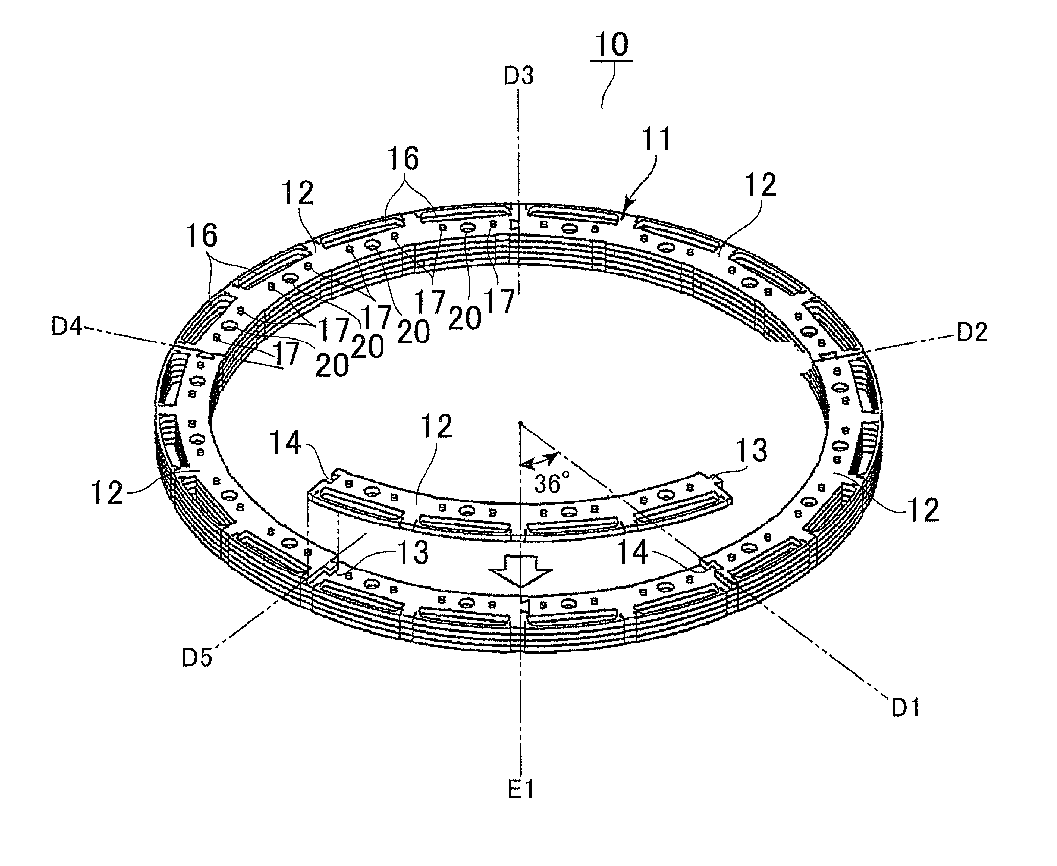
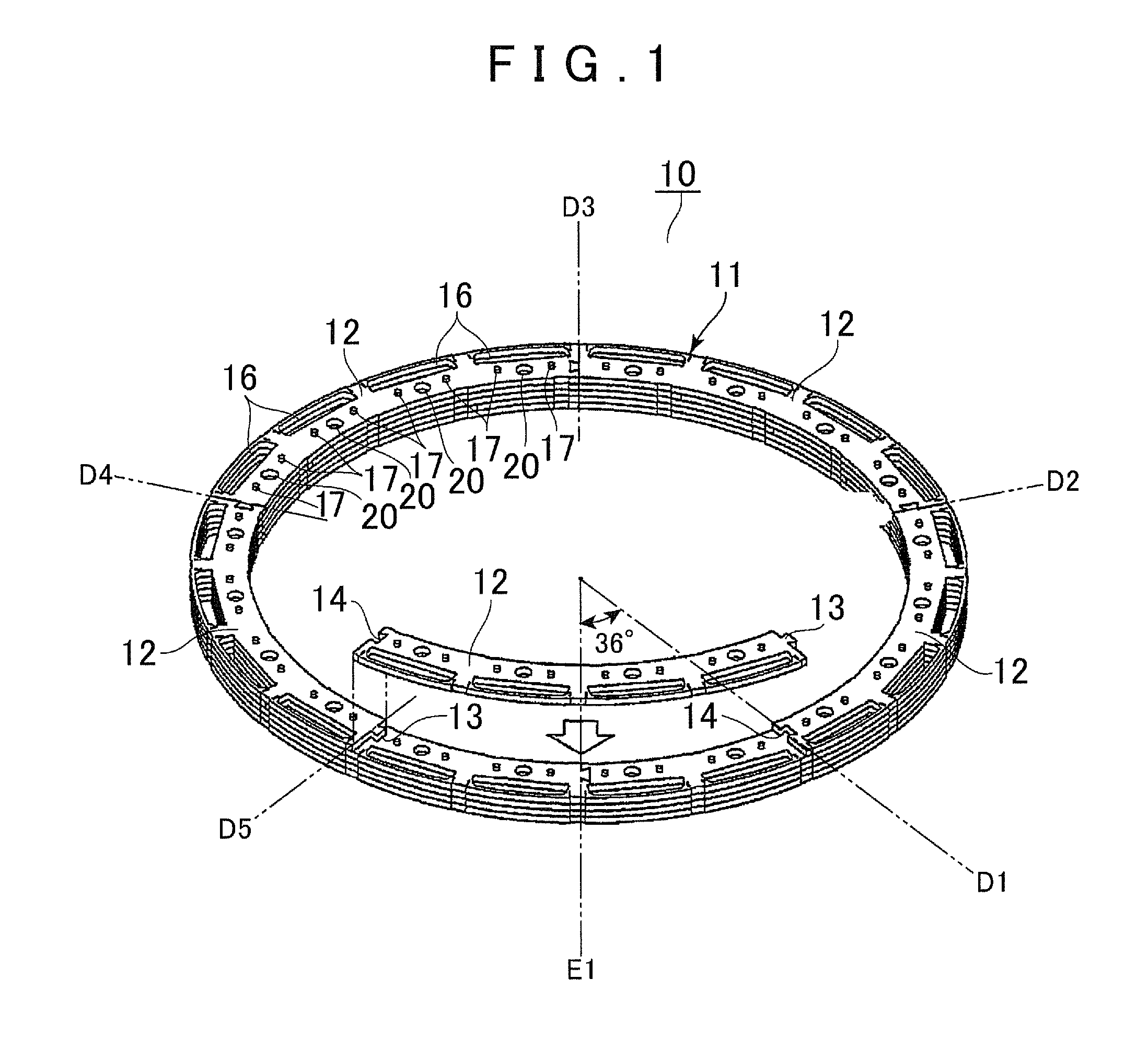
[0038]A first embodiment of the present invention will be described below with reference to the accompanying drawings. In the following description, radially outside refers to the side in the direction of a centrifugal force that acts on a pin extending through a rotor core, and the stacking direction refers to the direction in which core plates are stacked and refers to the same direction as the axial direction of a rotating shaft when the rotor core is attached to a rotor hub.

[0039]As shown in FIG. 1, a rotor core 10 for an interior permanent magnet (IPM) synchronous motor (a rotating electrical machine) has a cylindrical shape formed by stacking a plurality of annular core plates 11. In order to improve material yield, each core plate 11 is formed by a plurality of (in the present embodiment, five) core plate pieces 12 equally divided in the circumferential direction. Each core plate piece 12 is formed by an arc-shaped thin plate. Each core plate piece 12 has a protruding portion...


PUM


Abstract

A rotor of a rotating electrical machine includes a rotor core which includes an annular core plate formed by coupling a plurality of arc shaped core plate pieces. Multiple core plates are stacked together. A circumferential position of a seam formed by coupling the core plate pieces is alternately displaced for every predetermined number of core plates in a stacking direction of the core plates. A bar-shaped member is inserted in a plurality of through holes formed in the respective core plate pieces and aligned in the stacking direction. Both side surfaces of the rotor core in the stacking direction are interposed between end plates, the end plates contact the core plates, and the end plates do not contact the bar-shaped member at least on a radially outside of the bar-shaped member, which is a side in a direction of a centrifugal force that acts on the bar-shaped member.

Description

[0001]The disclosure of Japanese Patent Application No. 2011-286808 filed on Dec. 27, 2011 including the specification, drawings and abstract is incorporated herein by reference in its entirety.BACKGROUND OF THE INVENTION[0002]The present invention relates to a rotor of a rotating electrical machine including a rotor core formed by stacking core plates, and more particularly to a holding structure of the rotor core.DESCRIPTION OF THE RELATED ART[0003]Rotors of rotating electrical machines are typically known in the art in which a rotor core is formed by stacking annular core plates punched out from an electromagnetic steel plate and is fixed to a rotor hub. Conventionally, in order to improve material yield, it is proposed to form a rotor core by dividing each annular core plate into pieces in the circumferential direction, coupling the divided core plate pieces together in the circumferential direction, and stacking the resultant annular core plates in the axial direction (see Japa...

Claims


Application Information

Patent Timeline
Patent Type & Authority Applications(United States)
IPC IPC(8): H02K1/22
CPCH02K1/278H02K1/28
Inventor YAMAGUCHI, YASUOSANJI, HIROAKI
Owner AISIN AW CO LTD
Why Eureka
Try Eureka