Titanium fuel cell separator

a fuel cell separator and titanium technology, applied in the field of titanium fuel cell separators, can solve the problems of inferior strength and toughness of separation devices, high cost, and inability to meet the requirements of high-temperature separation, and achieve better conductivity, better durability, and higher adhesion.

Inactive Publication Date: 2013-06-27
KOBE STEEL LTD
View PDF3 Cites 13 Cited by
  • Summary
  • Abstract
  • Description
  • Claims
  • Application Information

AI Technical Summary

Benefits of technology

[0028]The titanium fuel cell separator according to the present invention, as having an intermediate layer including conductive titanium carbide, can have better conductivity, better durability, and higher adhesion.
[0029]The titanium fuel cell separator according to the present invention, when containing graphite in the carbon layer, may have further better conductivity and durability.
[0030]In addition, the titanium fuel cell separator according to the present invention, when having an average size of the titanium carbide grains constituting the intermediate layer of 5 nm or more, may have satisfactory adhesion between the substrate and the carbon layer.

Problems solved by technology

These separators, however, have inferior strengths and toughness and may be broken upon application of vibration or impact, although they have satisfactory corrosion resistance.
The noble metal materials are, however, very expensive and cause higher cost.

Method used


Image

  • Titanium fuel cell separator
  • Titanium fuel cell separator
  • Titanium fuel cell separator

Examples


examples

[0067]The titanium fuel cell separator according to the present invention will be illustrated in detail below, with reference to examples satisfying conditions specified in the present invention, and comparative examples not satisfying the conditions.

Specimen Preparation

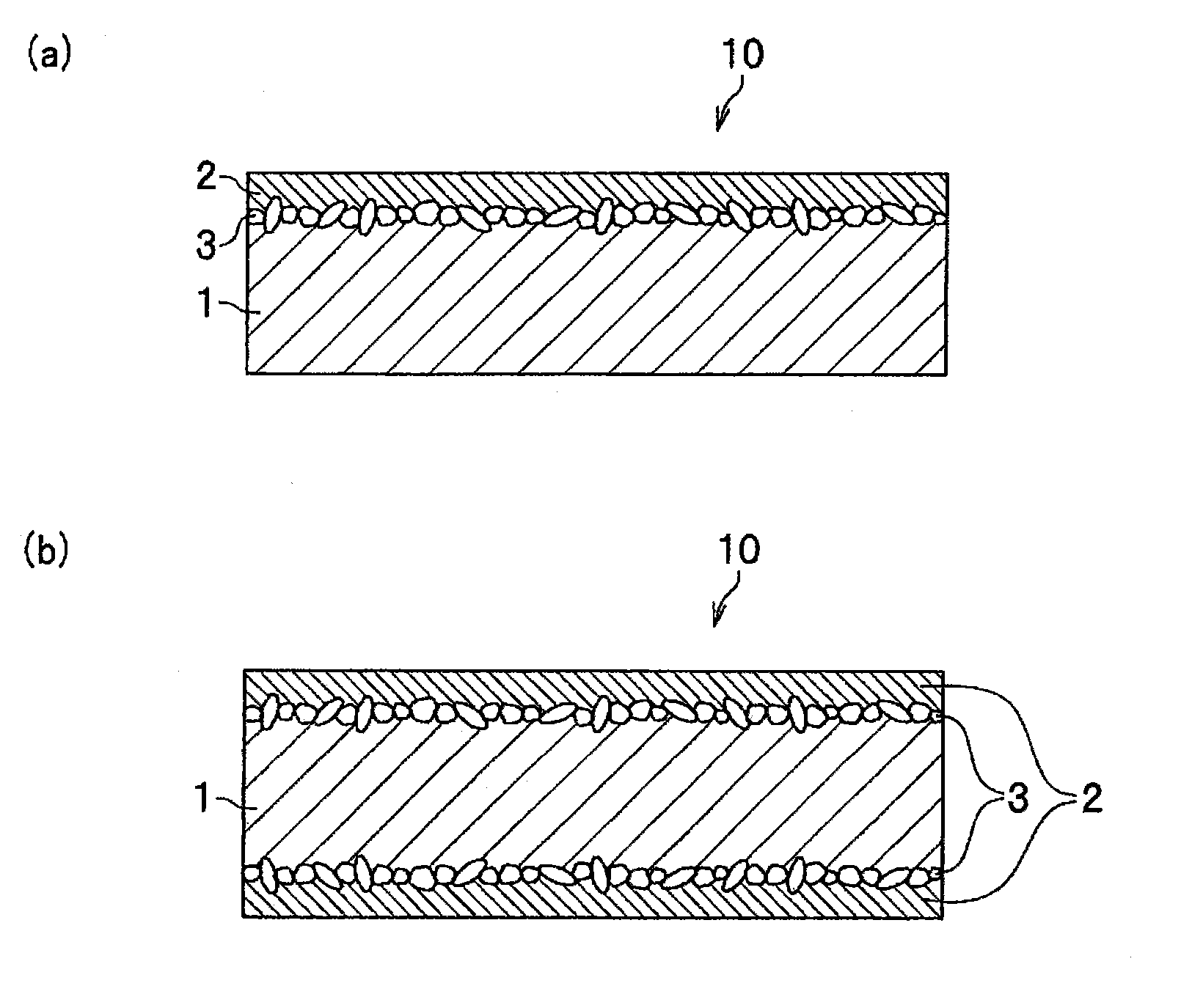
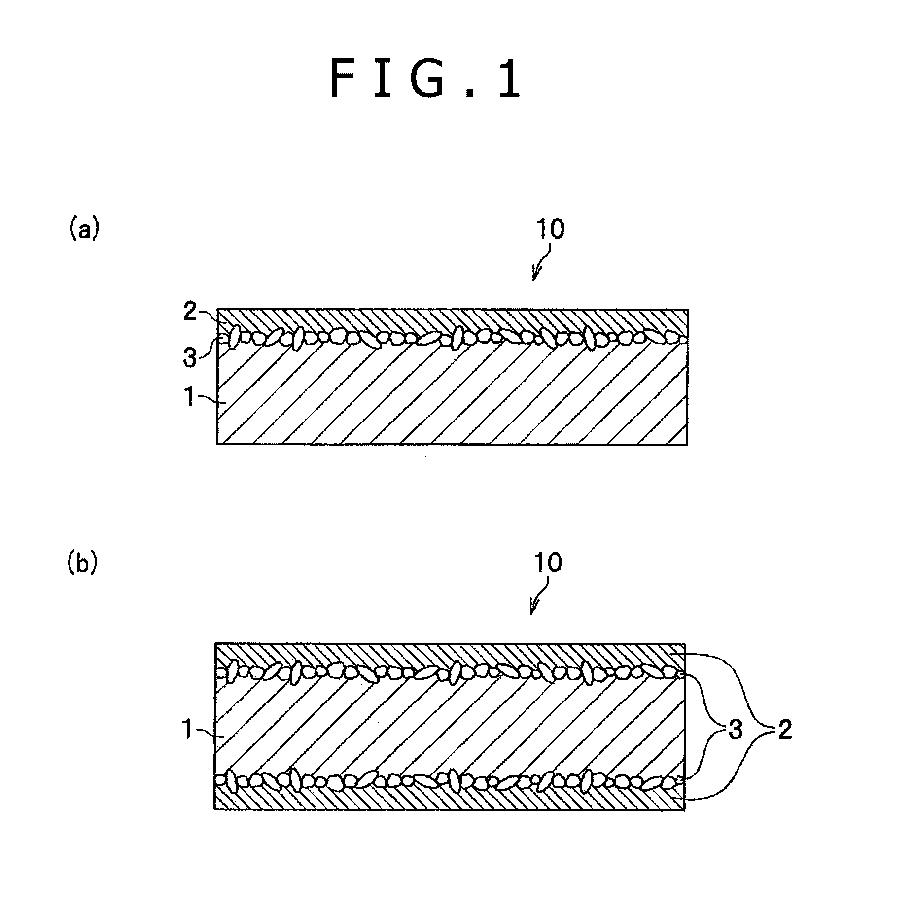
[0068]Pure titanium of JIS Class 1, which had undergone annealed and picked finish, was used as a substrate. The pure titanium had a chemical composition including oxygen (O) in a content of 450 ppm, iron (Fe) in a content of 250 ppm, and nitrogen (N) in a content of 40 ppm and further including titanium and inevitable impurities. The titanium substrate had a thickness of 0.5 mm. A carbon powder having an average particle size of 10 μm and four-nines purity was used. The titanium substrate was obtained by subjecting a titanium material sequentially to a melting step, casting step, hot rolling step, and cold rolling step according to known procedures.

[0069]The carbon powder was dispersed to a predetermined concentrat...


PUM

PropertyMeasurementUnit
sizeaaaaaaaaaa
thicknessaaaaaaaaaa
thicknessaaaaaaaaaa

Abstract

Disclosed is a titanium fuel cell separator having excellent conductivity and durability. In the disclosed titanium fuel cell separator (10), a carbon layer (2) is formed on the surface of a substrate (1) formed from pure titanium or a titanium alloy. An intermediate layer (3) is formed on the interface between the substrate (1) and the carbon layer (2). The intermediary layer (3) has lined-up granular titanium-carbide in the direction parallel to the carbon layer (2).

Description

TECHNICAL FIELD[0001]The present invention relates to titanium fuel cell separators for use in fuel cells.BACKGROUND ART[0002]Fuel cells are capable of continuously generating electric power through continuous supply of a fuel (e.g., hydrogen) and an oxidizing agent (e.g., oxygen). Unlike primary batteries (such as dry batteries) and secondary batteries (such as lead storage batteries), the fuel cells generate electric power at a high power generating efficiency without being significantly affected by the scale of an electric-power-using system and do not generate much noise and vibrations. The fuel cells are therefore expected to be used as energy sources covering a wide variety of uses and scales. Specifically, the fuel cells have been developed as polymer electrolyte fuel cells (PEFCs), alkaline fuel cells (AFCs), phosphoric acid fuel cells (PAFCs), molten carbonate fuel cells (MCFCs), solid oxide fuel cells (SOFCs), and biofuel cells. Among them, polymer electrolyte fuel cells h...

Claims


Application Information

Patent Timeline
Patent Type & Authority Applications(United States)
IPC IPC(8): H01M8/02
CPCH01M8/0206Y02E60/50H01M8/0228H01M8/0208H01M8/02H01M8/10
Inventor SUZUKI, JUNSATO, TOSHIKI
Owner KOBE STEEL LTD
Why Eureka
Try Eureka